
 E-submission
 KOTA
KOTA TOTA
TOTA TOTS
TOTS
Articles
- Page Path
- HOME > > Ahead-of print articles > Article
-
Original Article
- Multiple blocking screws reduce peak stress in a smaller-diameter tibial nail to a level similar to that in a canal-filling nail: a comparative finite element analysis
-
Jungtae Ahn1
 , Se Lin Jeong2, Gu-Hee Jung3
 -
DOI: https://doi.org/10.12671/jmt.2026.00255
Published online: October 13, 2026
1Department of Orthopedic Surgery, Gyeongsang National University Hospital, Gyeongsang National University College of Medicine, Jinju, Korea
2Department of Orthopedic Surgery, Gyeongsang National University Changwon Hospital, Gyeongsang National University College of Medicine, Changwon, Korea
3Department of Orthopedic Surgery, GIJANG Hospital, Busan, Korea
- Correspondence to: Gu-Hee Jung Department of Orthopedic Surgery, GIJANG Hospital, 6 Daecheong-ro 72beon-gil, Gijang-eup, Gijang-gun, Busan 46072, Korea Tel: +82-51-723-0171 Email: jyujin2001@hotmail.com
• Received: July 22, 2026 • Revised: August 31, 2026 • Accepted: September 10, 2026
© 2026 The Korean Orthopaedic Trauma Association
This is an Open Access article distributed under the terms of the Creative Commons Attribution Non-Commercial License (http://creativecommons.org/licenses/by-nc/4.0/) which permits unrestricted noncommercial use, distribution, and reproduction in any medium, provided the original work is properly cited.
- 91 Views
- 2 Download


Abstract
-
Background Cortical contact at the medullary isthmus permits cortical load sharing and constrains nail motion, and is considered important for stable intramedullary nailing. Blocking screws may provide the latter function. This finite element analysis examined whether adding multiple blocking screws to a smaller-diameter nail would reduce peak nail stress to a level similar to that of a canal-filling construct.
-
Methods Three configurations were modeled in a tibia with a 5-mm diaphyseal defect at the isthmus: an 11-mm canal-filling nail (model A), an 8-mm nail alone (model B), and an 8-mm nail with four 3.5-mm blocking screws positioned circumferentially (model C). An 800-N static axial load was applied at a medial-to-lateral ratio of 3:2 with the distal end fixed. Total deformation and von Mises stresses in bone, nail, and screws were analyzed using a linear elastic, small-deformation formulation.
-
Results Maximum total deformation was 5.60, 33.33, and 18.82 mm in models A, B, and C, respectively, occurring at the proximal tibia in all models. Peak nail stress in model B was 891.9 MPa, slightly exceeding the assumed 880-MPa yield threshold, whereas peak stresses were similar in models A (272.9 MPa) and C (265.8 MPa). Screw stress was asymmetric: 57.9 and 58.2 MPa in the posterior and medial screws versus 3.2 and 6.8 MPa in the lateral and anterior screws, indicating differential mechanical engagement of the blocking screws.
-
Conclusions Under the single static loading condition evaluated, four circumferential blocking screws reduced the peak nail stress of a smaller-diameter nail to a level similar to that of a canal-filling nail. Total deformation nevertheless remained approximately 3.4 times that of the canal-filling construct, and peak bone stress differed between constructs. The asymmetric screw-stress distribution was consistent with differential mechanical engagement of the blocking screws. Mechanical equivalence was not established for outcomes other than peak nail stress.
-
Level of evidence Not applicable.
Introduction
Intramedullary (IM) nailing is the standard of care for tibial diaphyseal fractures [1]. Nail diameter is a principal determinant of construct stiffness, and a canal-filling nail generally yields a stable construct. Donegan et al. defined the optimal nail-to-canal diameter ratio as 0.8 to 0.99, and reported a 4.4-fold increase in nonunion risk for constructs falling outside this range [2]. However, a canal-filling nail cannot always be used in clinical practice. A smaller-diameter nail may be required when the medullary canal is constitutionally narrow or when cortical thinning makes aggressive reaming unsafe. Under these conditions the nail no longer fills the canal, and the residual gap permits nail motion at the fracture site, which has been shown to compromise construct stability in biomechanical testing [3].
Blocking screws, also termed Poller screws, were introduced as an adjunct to IM nailing by Krettek et al. [3,4] in 1999. A blocking screw is inserted into the space between the nail and the endosteal cortex, thereby functionally narrowing the medullary cavity, guiding the nail toward the desired position, and enhancing construct stability [3,5]. Clinical studies have shown that blocking screws are effective for obtaining and maintaining alignment in tibial fractures [4,6].
Blocking screws have been described primarily as an adjunct for fracture reduction—that is, guiding the trajectory of the nail and preventing loss of alignment. A recent finite element (FE) study reported position-dependent changes in construct stiffness and stress distribution when a single Poller screw was placed at various locations and planes in distal tibial fractures [7]. Our previous FE analysis quantified screw-level stress in distal metaphyseal tibial fixation but examined only a single nail diameter and did not address the diaphyseal region [8]. A “fourth-generation” configuration has been proposed in which four blocking screws are placed around the nail in both the anteroposterior (AP) and mediolateral (ML) planes to provide coronal and sagittal stability, yet biomechanical validation of this circumferential configuration has not been reported [9]. Current data are therefore insufficient to fully characterize how stress is distributed across a construct that combines a small-diameter nail with multiple blocking screws, particularly when cortical load sharing across the fracture is removed and the load-constraining role traditionally attributed to isthmic cortical contact (ICC) must be borne entirely by the nail-screw construct.
The purpose of the present study was to analyze the stress distribution and construct stability of a small-diameter IM nail augmented with multiple blocking screws in a tibial diaphyseal bone defect model using FE analysis. The defect was introduced as a controlled worst-case condition that removes cortical load sharing across the fracture, thereby isolating the mechanical contribution of the blocking screws. We hypothesized that adding multiple blocking screws would reduce the peak nail stress of a smaller-diameter construct to a value similar to that of a canal-filling nail, and that the peak stresses developed in the individual screws would be asymmetric under the eccentric loading condition tested.
Methods
The study involved neither human participants nor animals, and institutional review board approval was therefore not required.
This was a nonclinical, in silico comparative biomechanical study using FE analysis. Three predefined FE constructs were compared under identical loading and boundary conditions. A 5-mm diaphyseal bone defect was incorporated at the tibial isthmus to remove cortical load sharing across the fracture, thereby allowing the mechanical effects of nail diameter and blocking-screw augmentation to be compared.
The three-dimensional models were constructed and processed using SolidWorks 2019 (Dassault Systèmes) and exported to ANSYS ver. 19.0 (ANSYS Inc.) for final mesh generation and FE analysis.
Model geometry and bone defect
The FE model was based on the three-dimensional computer-aided design (CAD) data of a commercial fourth-generation composite tibia (Sawbones; Pacific Research Laboratories). Fourth-generation composite bones reproduce the axial, bending, and torsional behavior of human long bones with markedly lower interspecimen variability and are regarded as an acceptable substitute for cadaveric specimens in biomechanical studies [10]. An IM nail fixation system for the tibial diaphysis was constructed in three dimensions using SolidWorks 2019 (Dassault Systèmes). The IM nail was modeled based on the Zimmer Natural Nail (Zimmer Biomet). The tibial and implant geometries were adapted from the model used in our previous analysis of distal tibial nailing [8].
Compared with our previous distal tibial model [8], the fracture was relocated to the diaphyseal isthmus and represented by a 5-mm segmental defect. Nail diameter is quoted here as the nominal distal shaft diameter. Consistent with the design of the Zimmer Natural Nail system, the proximal body of both the 8-mm and the 11-mm nail measures 11 mm over its proximal 60 mm, so the two constructs differ in diameter only distal to that segment; the shaft of the smaller nail also tapers slightly and is not of uniform 8-mm diameter along its length. The geometry of the tibia and implants was processed and refined within the SolidWorks platform. The defect was created as a transverse gap centered approximately 180 mm distal to the proximal articular surface and approximately 182 mm proximal to the distal articular surface in a tibia of approximately 367 mm overall length, corresponding to the level of the medullary isthmus. The fracture model was configured in the same CAD software and then exported to ANSYS ver. 19.0 (ANSYS Inc.) for adjustment of implant positioning and final mesh generation.
Fixation constructs
Three nail fixation constructs were modeled (Fig. 1). Model A consisted of an 11-mm-diameter nail with interlocking screws only. Model B consisted of an 8-mm-diameter nail with interlocking screws only. Model C consisted of the same 8-mm nail with four 3.5-mm blocking screws placed around the bone defect. In all three models, two proximal and two distal 5.0-mm interlocking screws were applied for a total of four interlocking screws.
Blocking-screw configuration
In model C, two blocking screws were positioned proximal to the defect and two distal, numbered 1 through 4 from proximal to distal. The insertion direction of each blocking screw and its position relative to the nail were as follows: screw 1 was inserted in the ML direction and lay posterior to the nail; screw 2 was inserted in the AP direction and lay lateral to the nail; screw 3 was inserted in the AP direction and lay medial to the nail; and screw 4 was inserted in the ML direction and lay anterior to the nail. This arrangement provided 360-degree support around the nail with the four blocking screws. Screws 1 and 4, both inserted in the ML direction, were positioned 42.75 mm from the adjacent margin of the defect, and screws 2 and 3, both inserted in the AP direction, were positioned 27.75 mm; all distances were measured to the screw axis. The arrangement was therefore symmetric about the defect. Each blocking screw was modeled bicortically, with its length adjusted to the local bone geometry so that the tip protruded approximately 2 mm beyond the far cortex; the individual screw lengths therefore differed between positions.
Each blocking screw was modeled with a minimal clearance from the nail rather than in initial contact, the clearance being small enough that the screw and the nail were effectively adjacent in the undeformed state. Because both the endosteal surface and the nail are curved and non-cylindrical, the clearance between the nail and the endosteal cortex varied around the circumference and along the length of the construct and could not be expressed as a single value; representative cross-sections taken at the level of the defect are shown in Fig. 1B.
The construct variables were nail diameter and the presence of blocking-screw augmentation. The outcome variables were total construct deformation and maximum von Mises stress (MPa) in the nail and bone. For model C, maximum von Mises stress in each of the four individual blocking screws was additionally evaluated. Peak nail stress was also expressed as a proportion of the assumed 880-MPa yield threshold of the titanium alloy.
Material properties
The material properties of the synthetic-bone model were adopted from our previous analysis using the same synthetic bone and implant system (Table 1) [8]. All implants were modeled as titanium alloy (Ti-6Al-4V; ASTM F1472) with linear elastic, homogeneous, and isotropic properties. A yield threshold of 880 MPa was assumed for the alloy, adopted from our previous analysis of the same implant system [8]; this is a representative annealed value for Ti-6Al-4V and is used here solely as a reference threshold rather than as a measured property of the implant. Because plasticity was not incorporated into the model, computed stresses exceeding this value indicate that yielding would be expected under the applied load rather than representing physically attainable stresses; peak stresses are accordingly reported both in absolute terms and as a proportion of the assumed threshold, as in earlier FE analyses of screw constructs [11].
Mesh generation
The bone and the nail were meshed with 10-node quadratic tetrahedral elements (SOLID187) at a uniform size of 2.0 mm, and the screws were meshed with 20-node hexahedral elements (SOLID186). Meshing produced 550,005 nodes and 373,729 elements in model A (372,991 tetrahedral and 738 hexahedral), 539,651 nodes and 368,322 elements in model B (367,734 and 588), and 554,950 nodes and 368,518 elements in model C (367,731 and 787). A uniform global element size was applied and no local mesh refinement was introduced at the nail-screw or screw-bone interfaces. This element size was consistent with that adopted in our previous FE analysis of the same nail and synthetic-bone model [8], and further refinement of the mesh produced no meaningful change in the peak von Mises stress within the nail; a separate convergence study at the level of the individual 3.5-mm blocking screws was not performed.
Contact conditions
Contact interactions between the implants and bone were defined according to the mechanical characteristics of each interface. Bonded contact, which presumes complete bonding at the screw-bone interface as assumed in comparable analyses [11], was applied between cortical and cancellous bone, between bone and interlocking screws, and between bone and blocking screws. Frictional contact (coefficient of friction 0.2) was applied between bone and nail, between nail and interlocking screws, and between nail and blocking screws. Bonded contacts permitted neither sliding nor separation. Frictional contacts permitted both sliding, once the interfacial shear limit was exceeded, and separation of the contacting surfaces. Bonded contact was adopted at the screw-bone interfaces because screw threads were not modeled and the analysis was not intended to represent thread purchase or pullout; frictional contact was adopted at the nail-screw and nail-bone interfaces so that the nail could translate and separate relative to the screws and the endosteal surface, thereby allowing the blocking screws to constrain nail motion. The friction coefficient of 0.2 was adopted from previous FE analyses of bone-implant interfaces in the same implant system [8].
Loading and boundary conditions
A static axial load of 800 N was applied to the medial and lateral articular surfaces of the proximal tibia, distributed at a 3:2 medial-to-lateral ratio (480 N medial, 320 N lateral) to approximate the in vivo ML load distribution [12]. This ratio lies at the upper end of the 53% to 60% medial share reported at maximum load in instrumented in vivo measurements [12]. The distal end of the tibia was set as a fixed support applied to the distal articular surface, removing all six degrees of freedom.
Solution procedure
The problem was solved as a single load step in one substep. Geometric nonlinearity was not enabled, so the analysis corresponds to a small-deformation formulation; the implications of this assumption are addressed in the Discussion. All three models converged within the full load step, requiring between 10 and 13 cumulative equilibrium iterations.
Total deformation was computed at the construct level, and the maximum von Mises stress (MPa) was computed separately within the nail domain and the bone domain (cortical and cancellous bone combined) for each model. For model C, the maximum von Mises stress within each individual blocking screw was also computed. Peak nail stress was additionally expressed as a proportion of the assumed 880-MPa yield threshold.
Results were compared descriptively across the three deterministic FE models. No inferential statistical testing was performed because the constructs did not represent repeated independent observations. Differences between constructs were reported as absolute values and, where relevant, as relative differences or ratios.
Results
Total deformation was greatest in model B (33.33 mm), followed by model C (18.82 mm) and model A (5.60 mm) (Fig. 2). In all three models the maximum value occurred at the proximal tibia, remote from the defect, and corresponded to tilting of the proximal segment about the fixed distal end rather than to displacement at the defect itself. The addition of the four screws to the 8-mm nail reduced its deformation by approximately 44% (model C vs. model B), although the resulting value remained approximately 3.4 times that of model A.
Maximum nail and bone stresses likewise distinguished the three constructs (Table 2, Figs. 3, 4). Nail stress was 272.9 MPa in model A, 891.9 MPa in model B, and 265.8 MPa in model C, corresponding to 31%, 101%, and 30% of the assumed yield threshold of the alloy. The value in model B was approximately 3.3 times those in models A and C, which were similar to each other (Fig. 4). In model C, the peak nail stress occurred around the defect at the level of the blocking screws (Fig. 5). In model B the computed peak stress reached and slightly exceeded the assumed threshold, by approximately 1.4%. The ranking of peak bone stress did not simply mirror that of peak nail stress: bone stress was lowest in model A (32.4 MPa), intermediate in model C (38.7 MPa), and highest in model B (48.2 MPa) (Fig. 3). The location of the peak also differed: it occurred in the distal tibia in models A and B but in the proximal tibia in model C.
The peak stresses developed in the four blocking screws in model C were markedly asymmetric (Table 3). The posterior screw proximal to the defect (screw 1, ML orientation) and the medial screw distal to the defect (screw 3, AP orientation) developed the highest peak stresses, at 57.9 MPa and 58.2 MPa, respectively. The lateral screw proximal to the defect (screw 2, AP orientation) and the anterior screw distal to the defect (screw 4, ML orientation) developed substantially lower peak stresses, at 3.2 MPa and 6.8 MPa, respectively. The two higher-stress screws thus developed peak stresses approximately 8.5 to 18 times those of the two lower-stress screws, although all four screws carried non-zero stress. Because peak von Mises stress is a local measure and no force-based output was extracted, these values are consistent with relative differences in mechanical engagement among the screws but do not quantify the proportion of the total load transmitted through each screw. The two higher-stress screws lay posterior and medial to the nail on the proximal and distal sides of the defect, respectively, whereas the two lower-stress screws lay lateral and anterior. The differences among the three constructs in total deformation and in peak bone and nail stress are summarized in Fig. 6.
Discussion
In this study, the addition of multiple blocking screws to a smaller-diameter IM nail produced a peak nail stress similar to that of a canal-filling nail and substantially lower than that of the same smaller-diameter nail used without blocking screws. Total deformation was reduced by approximately 44% relative to the unaugmented smaller nail but remained approximately 3.4 times that of the canal-filling construct, and peak bone stress was likewise not equivalent, so the correspondence observed here was confined to peak nail stress and did not extend across the other outcome measures. The peak stresses developed in the individual blocking screws were markedly asymmetric. In a diaphyseal defect model in which cortical load sharing was removed, these findings indicate that multiple blocking screws can reduce the peak nail stress of a smaller-diameter construct toward that of a canal-filling nail under the static loading condition tested; they do not establish overall mechanical equivalence between the two constructs.
Model B, the smaller nail used alone, was the least stable construct, and its elevated nail stress reflects this vulnerability. The cadaveric literature is consistent with this finding. Penzkofer et al. [13] reported that an 11-mm nail produced significantly less interfragmentary movement than a 9-mm nail and recommended the use of the largest feasible nail diameter. Augat et al. [14] extended this observation, demonstrating that the clearance between nail and canal, rather than the flexibility of the nail itself, was the principal determinant of interfragmentary movement under axial and shear loading. The behavior of model B is consistent with this observation. Model C, by contrast, approached model A in peak nail stress, a result consistent with the screws occupying the nail-cortex gap and constraining nail motion in a manner analogous to ICC in a canal-filling construct [3], although the present analysis did not measure that constraint directly.
The absolute magnitude of the values obtained in model B warrants comment. A total deformation of 33.33 mm is not a displacement that a loaded human tibia would sustain; it follows from the boundary conditions adopted here, in which a 5-mm defect removes all cortical contact across the fracture and the distal tibia is rigidly fixed, so that the entire load path passes through the implant. The maximum deformation occurred at the proximal tibia and represents tilting of the whole proximal segment about the fixed distal end, and it is therefore not a measure of interfragmentary motion at the defect. A further consideration is that the analysis was solved under a small-deformation formulation, without geometric nonlinearity. A deformation of this magnitude lies beyond the range over which that assumption is ordinarily regarded as accurate. Because the deformation predicted for model B is large relative to the assumptions of a small-deformation formulation, the absolute deformation and stress values for this construct should be interpreted with caution. The values reported in this study are therefore intended for relative comparison among constructs modeled under identical assumptions rather than as predictions of in vivo displacement or stress. Within this linear-elastic model, the peak nail stress in model B reached 891.9 MPa, approximately 1.4% above the assumed 880-MPa yield threshold [8]. Because the analysis was linear elastic and no plasticity was modeled, a computed stress of this magnitude indicates that yielding would be expected under this loading condition; it is not a demonstration that the implant would fail, and no fatigue analysis was performed. The model also omits the fibula, which in vivo carries part of the axial load of the leg, so the entire load path is concentrated through the tibial construct; this further exaggerates the demand placed on the nail in model B and reinforces the view that these values are worst-case and comparative rather than predictive. Within the present model, the unsupported 8-mm nail reached the assumed yield threshold, whereas the addition of four blocking screws reduced peak nail stress to approximately 30% of that threshold. Experimental observation is consistent with this reading: in a synthetic-tibia model fixed with a 9-mm nail, all constructs survived 10,000 ML loading cycles without hardware deformation, but under a subsequent 350-N failure test nail loosening and nail bending occurred exclusively in specimens without blocking screws [15].
Blocking screws have traditionally been regarded as an adjunct for fracture reduction [4-6]. The present findings suggest an additional mechanical role: following nail fixation, the blocking screws can become mechanically engaged, and their presence was associated with a reduction in the peak stress developed in the nail. Krettek et al. [3], in cadaveric metaphyseal specimens loaded in ML bending, reported a 25%–57% reduction in construct deformation after blocking screw insertion. Zhang et al. [15], testing synthetic tibiae under ML loading, likewise reported reductions of 26.2% and 28.9% in maximum construct displacement with conventional and modified blocking screws, respectively. The present study examined a different configuration—a diaphyseal defect under axial loading, with nail stress as the primary outcome—and observed a comparable direction of effect. The configuration is itself recent: a “fourth-generation” arrangement positions four screws circumferentially to stabilize both the coronal and sagittal planes on either side of the fracture [9], yet it had not been characterized mechanically. The present data provide a first characterization of this configuration under a single static loading condition, in which the four-screw construct reached a peak nail stress similar to that of a canal-filling nail. The arrangement examined here is an idealized biomechanical one; its anatomical feasibility, the additional operative burden it imposes, and any clinical benefit were not assessed. On this basis, the screws appear to contribute mechanically beyond their role as a reduction adjunct, which may partly offset the loss of the load-constraining role attributed to ICC.
Peak stress among the four screws was markedly uneven. Under the 3:2 medial-to-lateral load, screw 1 (posterior) and screw 3 (medial) developed the highest peak stresses, whereas screw 2 (lateral) and screw 4 (anterior) developed much lower values. This pattern is consistent with a posteromedial toggle of the nail driven by the eccentric load, the screws opposing that displacement being the most strongly engaged. The classical recommendation to place a blocking screw on the concave side of the deformity [5] is thus consistent with the present peak-stress distribution. Because displacement vectors and contact-pressure distributions were not extracted, however, this mechanism is presented as a model-based inference rather than as a directly demonstrated finding. This does not render screws 2 and 4 redundant. The model was loaded in a single static axial direction, whereas in vivo loading varies in direction and magnitude throughout the gait cycle [12]; when the direction of toggle changes, a screw that was minimally engaged under the present condition may become the principal load-bearing element. This is a hypothesis that the present analysis does not test, since only one loading direction was examined, and the four-direction arrangement should not be regarded as a generally validated default on the basis of these data.
Bone stress in model C (38.7 MPa) was intermediate between model A (32.4 MPa) and model B (48.2 MPa), indicating that the three constructs produced different local stress distributions within the bone. Because only peak von Mises stress was extracted and no contact or reaction forces were computed, these values should not be interpreted as direct measures of load sharing. Whether the intermediate bone stress observed in model C represents a biologically favorable mechanical environment cannot be determined from the present model. As the applied load was static and axial, the implications of these differences for fracture healing remain to be established.
The present analysis further extends earlier screw-level work. A single-screw FE analysis addressed the position dependence of one Poller screw but not the distribution among multiple screws [7], and a previous distal tibial analysis reported an approximately 20%–27% reduction in stress around the distal interlocking screws with blocking screws [8]. A recent report on lower limb extra-isthmic fractures, which combined a meta-analysis with a FE analysis of the distal tibia, described the opposite direction of effect on implant stress in its FE component, which rose from 86.7 to 120.1 MPa when a Poller screw was added, while displacement at the fracture site fell by 54.9% [16]. The discrepancy is instructive. In that model the unaugmented construct was already stable, with fracture-site displacement of only 0.11 mm, so an additional screw introduced a further load path and raised implant stress. In the present model the unaugmented smaller nail was grossly overloaded across a defect, and the addition of the screws was associated with a lower peak nail stress rather than a higher one. The direction in which blocking screws shift implant stress therefore appears to depend on how far the baseline construct sits from mechanical failure, whereas the displacement measures reported were reduced in every case, although these were not the same quantity: global construct deformation in the present model and fracture-site displacement in the extra-isthmic analysis [16]. The pattern of stress redistribution therefore appears to reflect the loading condition, the screw orientation, and the stability of the baseline construct. In a systematic review of 13 studies comprising 371 patients, Tennyson et al. [17] reported low pooled proportions of nonunion (4%) and coronal malunion (5%) after blocking-screw augmentation, lower than the rates reported in the literature for nailing alone. The meta-analytic component of the extra-isthmic report cited above [16], pooling five comparative cohorts with 413 patients, found a higher union rate with Poller screws (odds ratio 2.48; 95% confidence interval 1.13–5.46) and fewer secondary procedures. The present study offers one possible mechanical basis for these observations. That relationship is hypothesis generating and does not establish a causal link between the modeled stress environment and clinical union.
This study has several limitations. First, although the use of a fourth-generation Sawbones composite tibia ensured high reproducibility [10], it does not fully capture the density variation and microstructure of human bone. Second, only a static axial load was applied; rotational and bending loads, as well as the dynamic load variation across the gait cycle, were not considered, and the 800-N load applied here is well below the peak tibial load recorded during gait and stair activity [12]. Third, screw threads were not modeled, so pullout and local micromotion at the screw-bone interface could not be represented; screw-bone contact was idealized as fully bonded, which overestimates the constraint at that interface. Fourth, the 5-mm defect used in this study is relatively small, and results may differ for larger defects. On the other hand, the presence of a defect itself eliminates cortical bridging across the fracture and thus represents a worst-case condition for the nail-screw construct, under which the correspondence in peak nail stress between the blocking-screw-augmented smaller nail and the canal-filling construct observed here was still preserved. Fifth, the analysis was based on a single tibial geometry, and the effect of anatomic variation on the results was not assessed. Sixth, the model was not validated against experimental mechanical testing, and no cadaveric or synthetic-bone measurements were available for direct comparison; the results should accordingly be read as relative comparisons among constructs sharing identical assumptions rather than as absolute predictions of construct performance. Protocols suitable for such validation have been described for synthetic tibiae under cyclic loading [15]. Seventh, the analysis used a small-deformation formulation and did not enable geometric nonlinearity; therefore, the absolute deformation and stress values, particularly for model B, should be interpreted with caution and regarded as comparative rather than as absolute predictions of construct behavior. Eighth, total deformation is a global construct-level measure and is not equivalent to interfragmentary motion at the defect; relative displacement between the fragments was not extracted. Ninth, the peak von Mises stresses reported for the individual blocking screws are local stress measures that may depend on element size and the contact assumptions adopted, and no convergence study was performed at the level of the individual screws. Tenth, peak von Mises stress is not a direct measure of load sharing; no contact or reaction forces were computed, so the proportion of load transmitted through each screw was not quantified. Eleventh, the fibula was not included in the model, so the load sharing that it provides in vivo was not represented, and the demand on the tibial construct is correspondingly overstated.
The present findings have practical implications when a smaller-diameter nail is required because of a narrow medullary canal or cortical thinning. Augmenting a smaller-diameter nail with multiple blocking screws lowered the modeled peak nail stress toward that of a canal-filling nail, providing a limited biomechanical rationale for this combination when a canal-filling nail cannot be used; it does not establish that the two constructs behave equivalently, since deformation and bone stress differed. The asymmetric peak stress among the four screws indicates that each screw's mechanical role is shaped by the direction of nail displacement rather than by its presence alone; since loading direction may vary with fracture configuration and weight-bearing pattern, these findings may complement existing anatomical and technical guidance on blocking screw placement [18] and may inform surgical planning, although further validation under dynamic and multidirectional loading is needed before specific placement recommendations can be made.
Under the single static loading condition tested, the addition of multiple blocking screws to a smaller-diameter IM nail reduced the modeled peak nail stress to a value similar to that of a canal-filling nail in a tibial diaphyseal bone defect model, although total deformation remained approximately 3.4 times that of the canal-filling construct and peak bone stress was intermediate rather than equivalent. Peak stress among the blocking screws was asymmetric, with the screws opposing nail toggle developing the highest values. These results support a mechanical role for blocking screws beyond their use as an adjunct for fracture reduction and suggest that, under the modeled conditions, they may partly offset the loss of the load-constraining role attributed to ICC. Equivalence in stiffness, interfragmentary stability, fatigue performance, or clinical outcome was not evaluated.
-
Author contributions
Conceptualization: GHJ. Methodology: SLJ, GHJ. Software: SLJ, GHJ. Validation: SLJ. Investigation: JA, SLJ, GHJ. Formal analysis: JA, SLJ, GHJ. Data curation: JA, SLJ. Visualization: JA, SLJ, GHJ. Supervision: GHJ. Project administration: GHJ. Writing–original draft: JA. Writing–review & editing: JA, GHJ. All authors read and approved the final manuscript.
-
Conflicts of interest
No potential conflict of interest relevant to this article was reported.
-
Funding
None.
-
Data availability
All data relevant to this study are presented in the tables.
-
Acknowledgments
None.
-
Supplementary materials
None.
Article Information
Fig. 1.
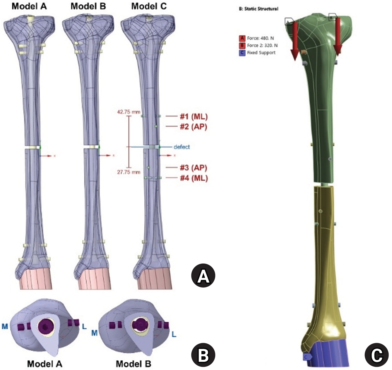
Structural overview of the three finite element models. (A) Anterior views of model A, comprising an 11-mm nail with interlocking screws; model B, comprising an 8-mm nail with interlocking screws; and model C, comprising an 8-mm nail with four blocking screws. In model C, the blocking screws are numbered 1–4 from proximal to distal, and their insertion directions are indicated. Screws 1 and 4 are positioned 42.75 mm from the margin of the defect, and screws 2 and 3 are positioned 27.75 mm, measured to the screw axis. (B) Axial cross-sections of models A and B at the level of the defect, corresponding to the medullary isthmus and viewed from distal to proximal. Cortical bone is shown in light violet, cancellous bone in pale yellow, and the implants in magenta. The screws visible in these sections are interlocking screws. Model C is not shown because its nail is identical to that in model B and its blocking screws lie outside the illustrated plane. (C) Loading configuration consisting of an 800-N static axial load—480 N medially and 320 N laterally—and fixed support at the distal articular surface. ML, mediolateral; AP, anteroposterior; L, lateral; M, medial.
Fig. 2.
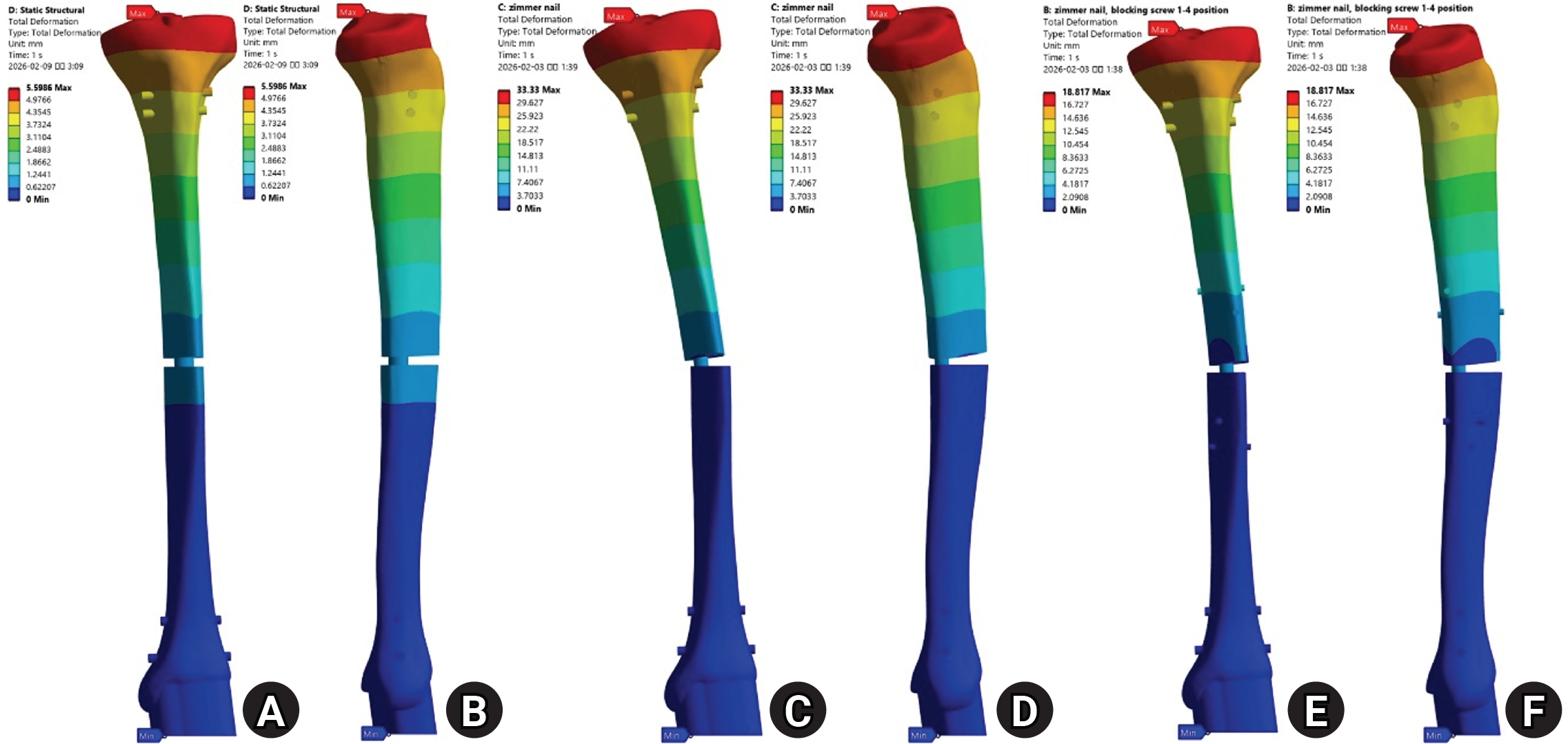
Total deformation under axial loading. Maximum deformation was 5.60 mm in model A (A, B), 33.33 mm in model B (C, D), and 18.82 mm in model C (E, F) and occurred at the proximal tibia in all three models. Anterior views are shown in (A), (C), and (E), and medial views in (B), (D), and (F). The color scale was adjusted separately to the maximum value for each model; therefore, color differences between panels should not be interpreted as differences in absolute deformation.
Fig. 3.
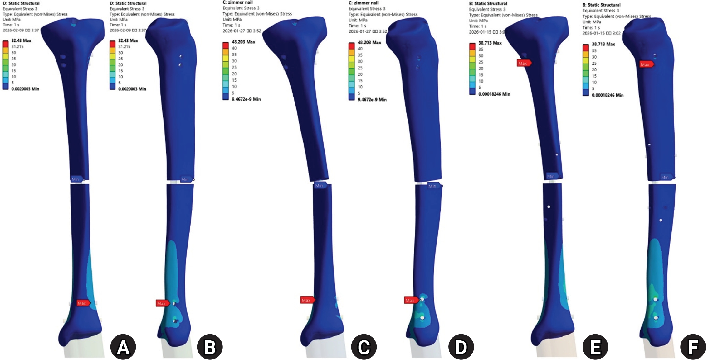
Distribution of von Mises stress in the bone under axial loading, calculated across the entire bone domain. Peak bone stress was 32.4 MPa in model A (A, B), 48.2 MPa in model B (C, D), and 38.7 MPa in model C (E, F). Anterior views are shown in (A), (C), and (E), and medial views in (B), (D), and (F). Contour bands are identical across panels except for the uppermost band, which extends to the model-specific maximum.
Fig. 4.
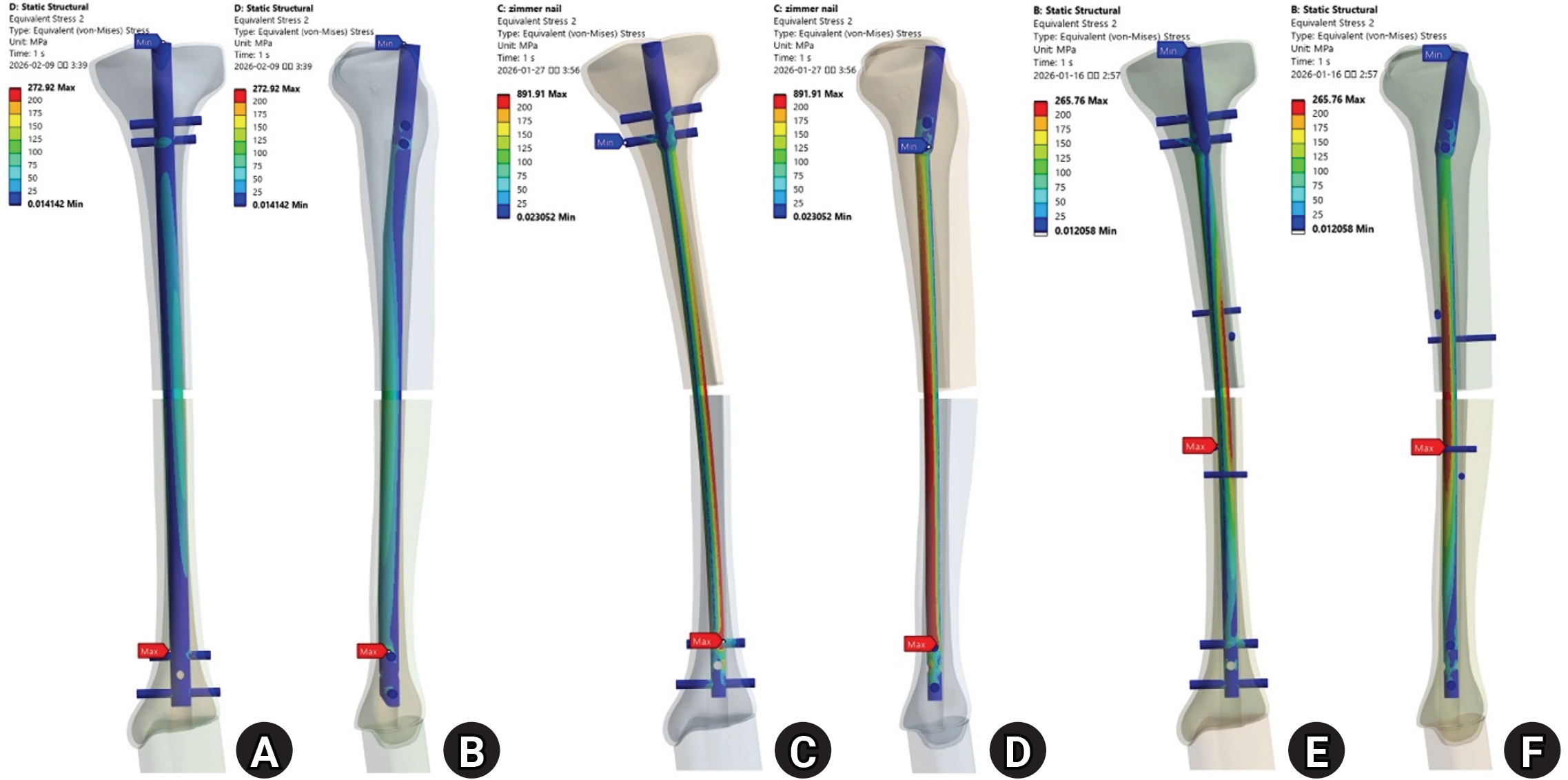
Distribution of von Mises stress in the nail under axial loading. Peak nail stress was 272.9 MPa in model A (A, B), 891.9 MPa in model B (C, D), and 265.8 MPa in model C (E, F). Anterior views are shown in (A), (C), and (E), and medial views in (B), (D), and (F). Model B shows regions of elevated stress along the nail at the defect level, whereas the peak stress magnitude in model C is comparable to that in model A, although in model C the peak occurs at the level of the blocking screws. Contour bands are identical across panels except for the uppermost band, which extends to the model-specific maximum.
Fig. 5.
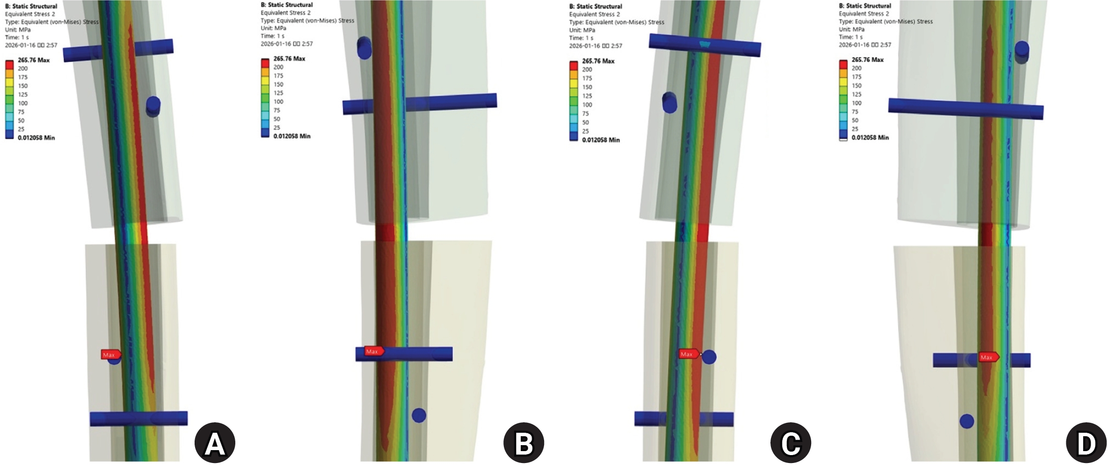
Magnified distribution of von Mises stress around the defect in the model C nail. (A) Anterior, (B) medial, (C) posterior, and (D) lateral views are shown. The maximum nail stress was 265.8 MPa. Peak stresses in the individual blocking screws are reported in Table 3.
Fig. 6.
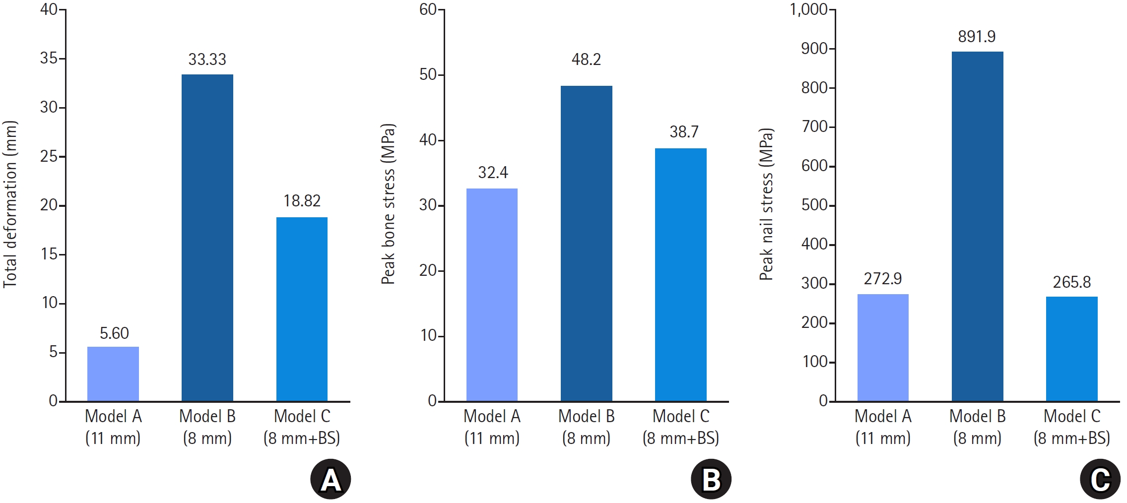
Quantitative comparison of the three models. (A) Total deformation was 5.60, 33.33, and 18.82 mm in models A, B, and C, respectively. (B) Peak bone stress was 32.4, 48.2, and 38.7 MPa, respectively. (C) Peak nail stress was 272.9, 891.9, and 265.8 MPa, respectively. BS, blocking screws.
Table 1.
Material properties assigned to the bone and implants
| Material | Density (g/cm³) | Young’s modulus (GPa) | Poisson’s ratio |
|---|---|---|---|
| Cortical bone | 1.5 | 10.7 | 0.33 |
| Cancellous bone | 0.2 | 0.524 | 0.35 |
| Titanium alloy (nail and screws) | 4.62 | 110 | 0.30 |
Values for cortical and cancellous bone were determined by mechanical testing of the specific synthetic-bone products used in this study (Sawbones 3403-33 and PFC20, respectively), performed in collaboration with partner laboratories, because the manufacturer does not publish complete mechanical property data; values for the titanium alloy were taken from the literature. All values were adopted from a previous study [8]. The implants were modeled as Ti-6Al-4V titanium alloy (ASTM F1472). A yield threshold of 880 MPa was assumed, adopted from our previous analysis of the same implant system [8].
Table 2.
Maximum von Mises stress (MPa) in each component under axial loading
| Component | Model A | Model B | Model C |
|---|---|---|---|
| Nail | 272.9 | 891.9 | 265.8 |
| Nail stress / assumed yield threshold (%) | 31 | 101 | 30 |
| Bone | 32.4 | 48.2 | 38.7 |
The assumed yield threshold for the titanium alloy is given in Table 1.
Model A, 11-mm nail with interlocking screws; model B, 8-mm nail with interlocking screws; model C, 8-mm nail with four blocking screws.
Table 3.
Maximum von Mises stress of individual blocking screws in model C
| Screw no. | Location | Orientation | Position relative to nail | Von Mises stress (MPa) |
|---|---|---|---|---|
| 1 | Proximal | ML | Posterior | 57.9 |
| 2 | Proximal | AP | Lateral | 3.2 |
| 3 | Distal | AP | Medial | 58.2 |
| 4 | Distal | ML | Anterior | 6.8 |
- 1. Duan X, Al-Qwbani M, Zeng Y, Zhang W, Xiang Z. Intramedullary nailing for tibial shaft fractures in adults. Cochrane Database Syst Rev 2012;1:CD008241.ArticlePubMedPMC
- 2. Donegan DJ, Akinleye S, Taylor RM, Baldwin K, Mehta S. Intramedullary nailing of tibial shaft fractures: size matters. J Orthop Trauma 2016;30:377-80.ArticlePubMed
- 3. Krettek C, Miclau T, Schandelmaier P, Stephan C, Möhlmann U, Tscherne H. The mechanical effect of blocking screws (“Poller screws”) in stabilizing tibia fractures with short proximal or distal fragments after insertion of small-diameter intramedullary nails. J Orthop Trauma 1999;13:550-3.ArticlePubMed
- 4. Krettek C, Stephan C, Schandelmaier P, Richter M, Pape HC, Miclau T. The use of Poller screws as blocking screws in stabilising tibial fractures treated with small diameter intramedullary nails. J Bone Joint Surg Br 1999;81:963-8.ArticlePubMedPDF
- 5. Stedtfeld HW, Mittlmeier T, Landgraf P, Ewert A. The logic and clinical applications of blocking screws. J Bone Joint Surg Am 2004;86 Suppl 2:17-25.Article
- 6. Ricci WM, O’Boyle M, Borrelli J, Bellabarba C, Sanders R. Fractures of the proximal third of the tibial shaft treated with intramedullary nails and blocking screws. J Orthop Trauma 2001;15:264-70.ArticlePubMed
- 7. Tan J, Yang Y, Wang M, et al. In silico biomechanical analysis of Poller screw-assisted small-diameter intramedullary nail in the treatment of distal tibial fractures. Front Bioeng Biotechnol 2023;11:1172013.ArticlePubMedPMC
- 8. Jung GH, Jeong SL, Ahn J. Stress distribution in interlocking and blocking screw fixation for distal tibial intramedullary nailing: a finite element analysis. J Clin Med 2025;14:4769.ArticlePubMedPMC
- 9. Zhou AK, Jou E, Lu V, Zhang J, Chabra S, Krkovic M. The evolution of Poller screws. EFORT Open Rev 2024;9:252-63.ArticlePubMedPMC
- 10. Elfar J, Menorca RM, Reed JD, Stanbury S. Composite bone models in orthopaedic surgery research and education. J Am Acad Orthop Surg 2014;22:111-20.ArticlePubMedPMC
- 11. Sensoz E, Özkal FM, Acar V, Cakir F. Finite element analysis of the impact of screw insertion distal to the trochanter minor on the risk of iatrogenic subtrochanteric fracture. Proc Inst Mech Eng H 2018;232:807-18.ArticlePubMedPDF
- 12. Zhao D, Banks SA, D’Lima DD, Colwell CW, Fregly BJ. In vivo medial and lateral tibial loads during dynamic and high flexion activities. J Orthop Res 2007;25:593-602.ArticlePubMed
- 13. Penzkofer R, Maier M, Nolte A, et al. Influence of intramedullary nail diameter and locking mode on the stability of tibial shaft fracture fixation. Arch Orthop Trauma Surg 2009;129:525-31.ArticlePubMedPDF
- 14. Augat P, Penzkofer R, Nolte A, et al. Interfragmentary movement in diaphyseal tibia fractures fixed with locked intramedullary nails. J Orthop Trauma 2008;22:30-6.ArticlePubMed
- 15. Zhang CM, Sun L, Wang Q, et al. A new technique for placement of blocking screws and its mechanical effect on stability of tibia fractures with distal fragments after insertion of small-diameter intramedullary nails. Orthop Surg 2021;13:2127-36.ArticlePubMedPMCPDF
- 16. Yang Z, Sheng B, Liu D, Lu Y, Chen B. The role of Poller screws in intramedullary nailing for lower limb extra-isthmic fractures. J Orthop Surg Res 2026;21:397.ArticlePubMedPMCPDF
- 17. Tennyson M, Krkovic M, Fortune M, Abdulkarim A. Systematic review on the outcomes of poller screw augmentation in intramedullary nailing of long bone fracture. EFORT Open Rev 2020;5:189-203.ArticlePubMedPMCPDF
- 18. Ahn J, Jeong SL, Jung GH. How to obtain the desired results from distal tibial nailing based on anatomy, biomechanics, and reduction techniques. J Musculoskelet Trauma 2025;38:74-85.ArticlePDF
References
Figure & Data
REFERENCES
Citations
Citations to this article as recorded by 
 ePub Link
 Cite
Cite XML Download
Multiple blocking screws reduce peak stress in a smaller-diameter tibial nail to a level similar to that in a canal-filling nail: a comparative finite element analysis
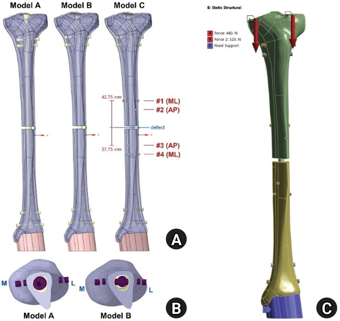
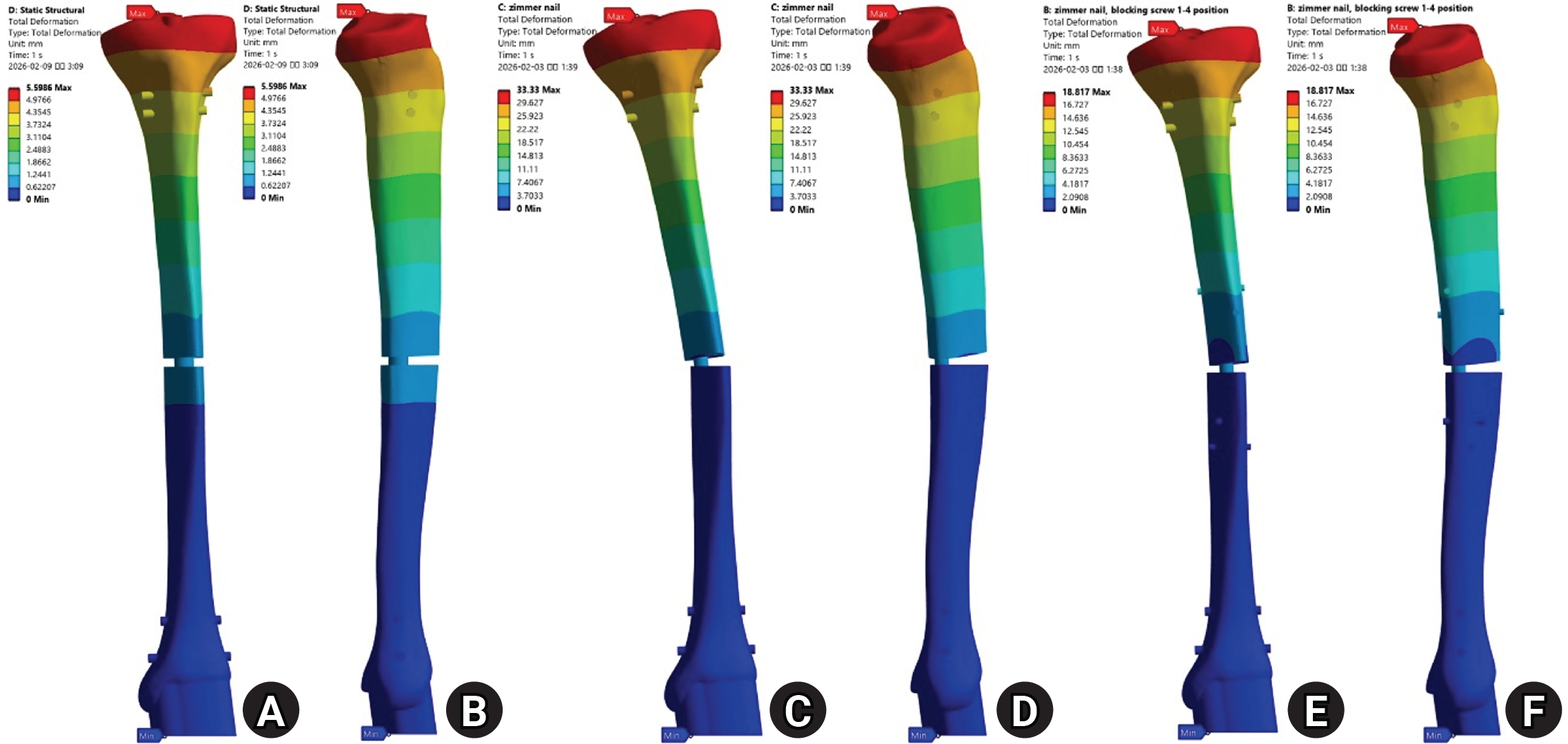
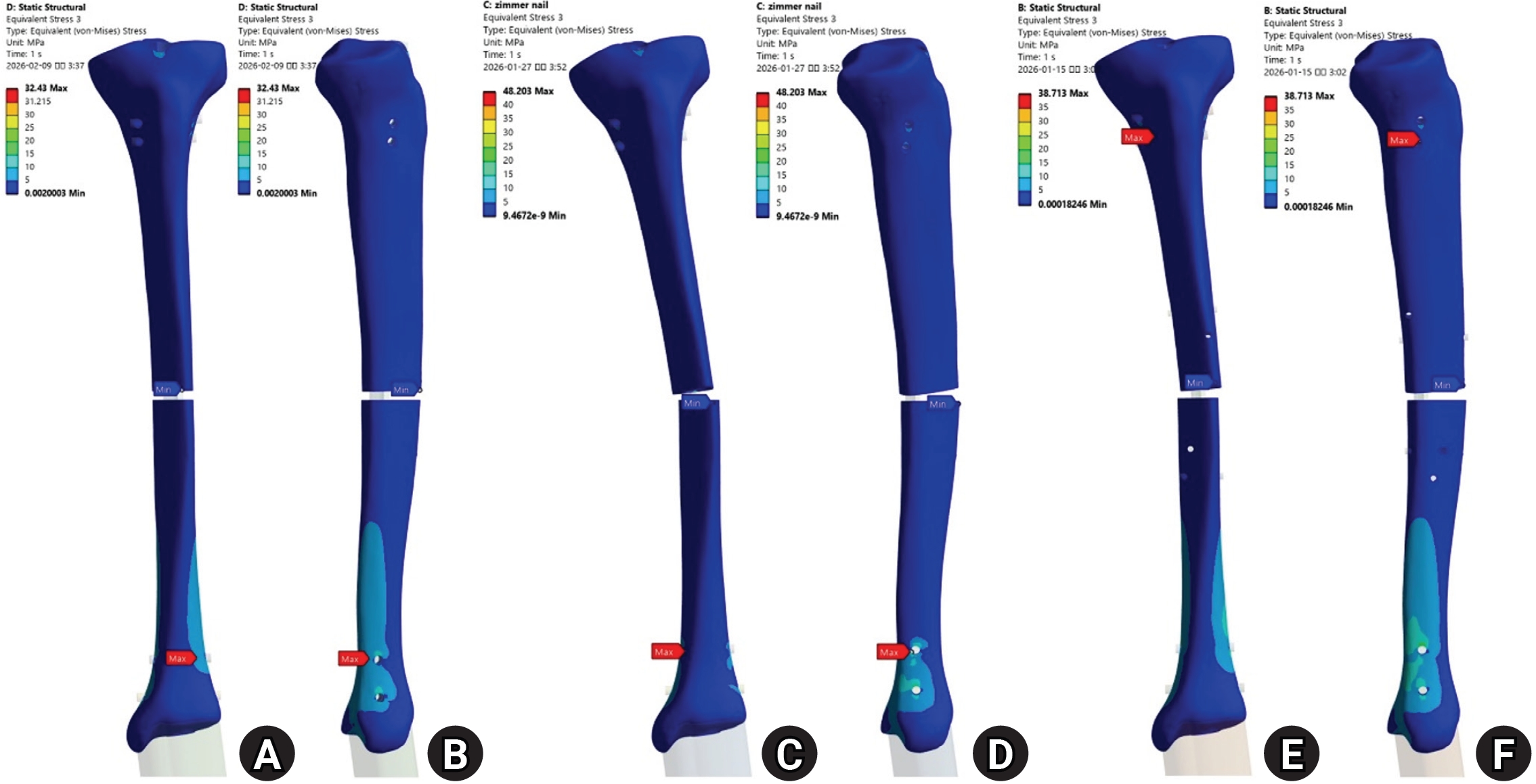
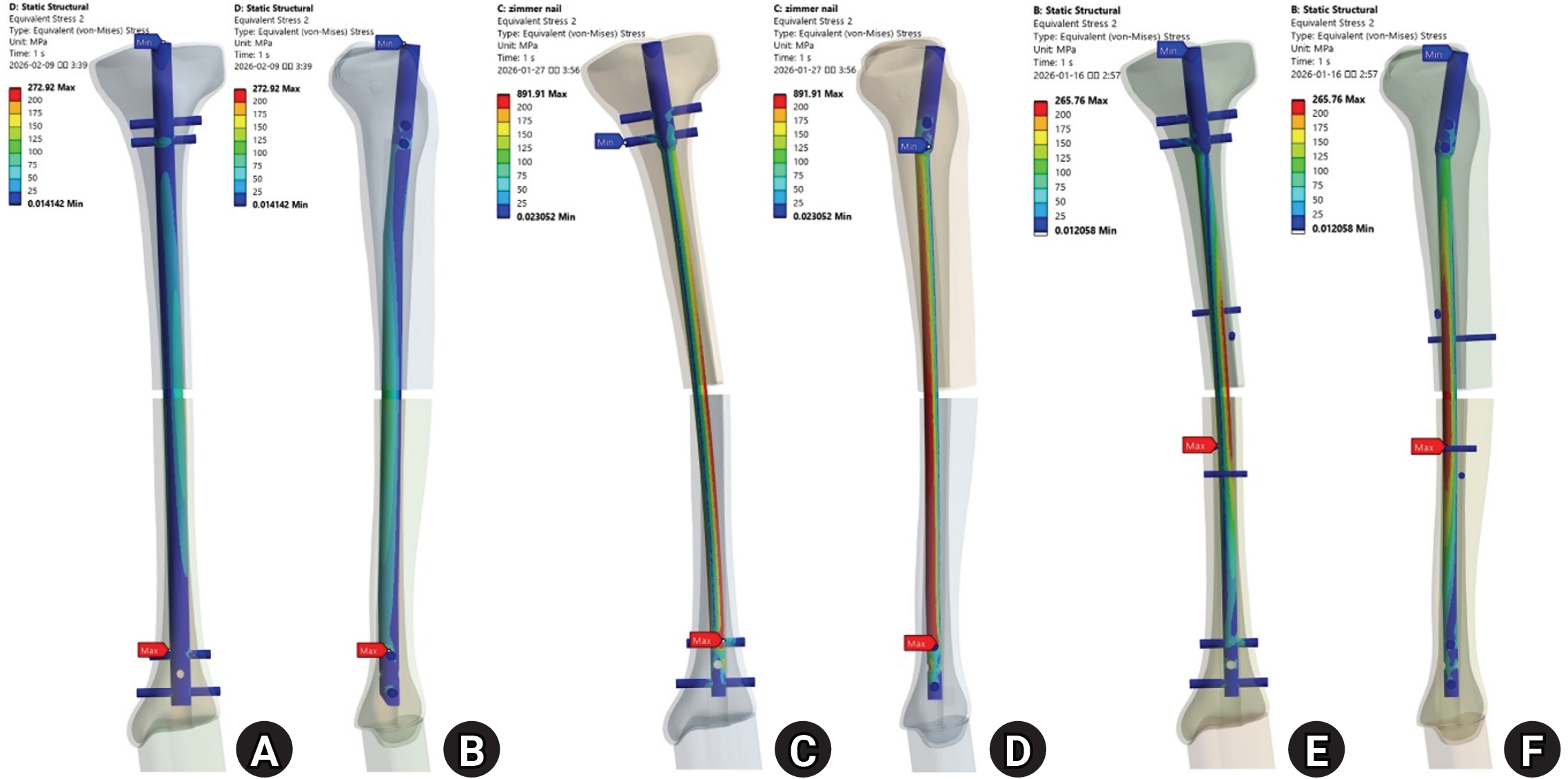
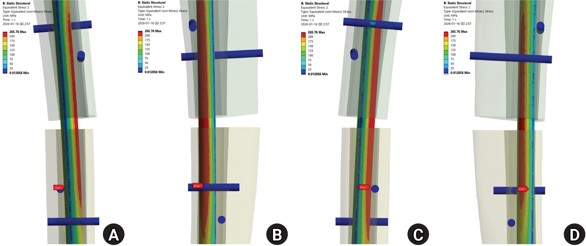
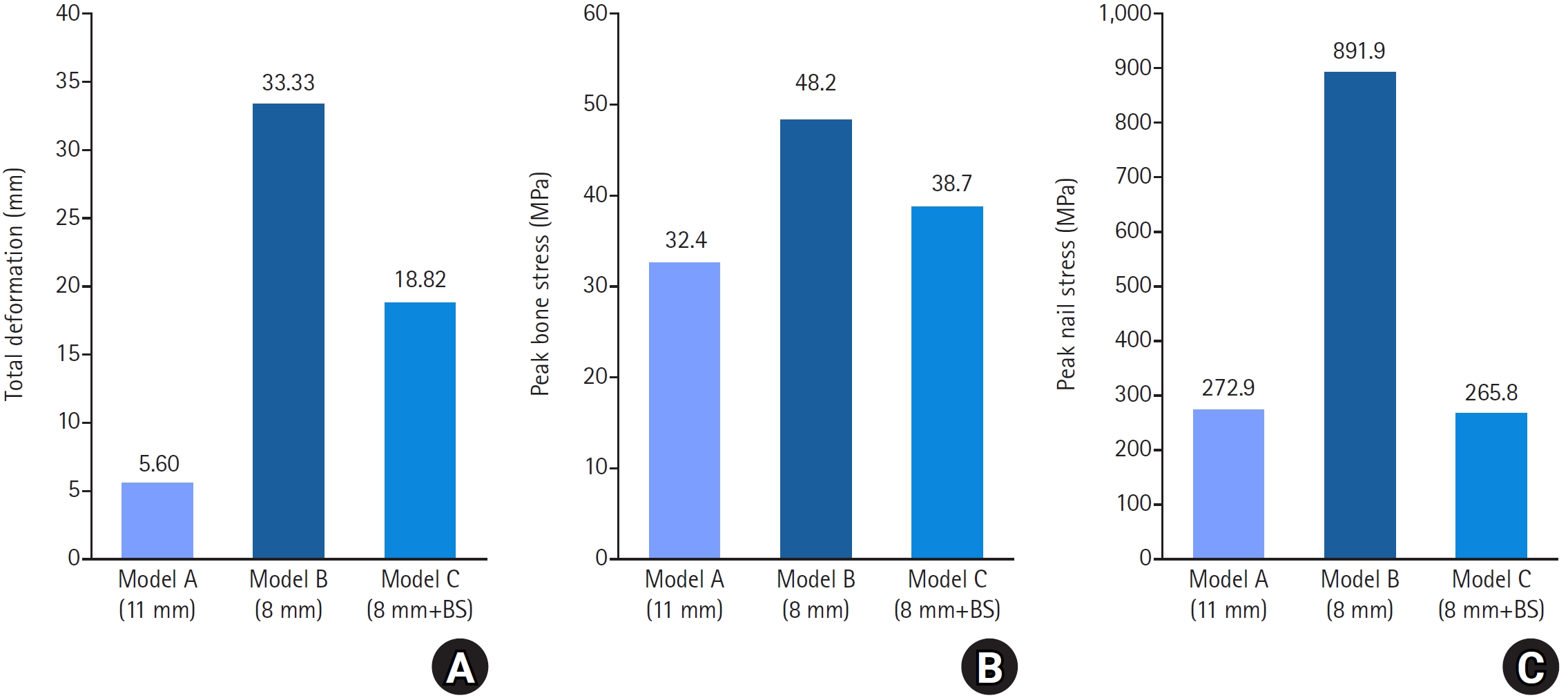
Fig. 1. Structural overview of the three finite element models. (A) Anterior views of model A, comprising an 11-mm nail with interlocking screws; model B, comprising an 8-mm nail with interlocking screws; and model C, comprising an 8-mm nail with four blocking screws. In model C, the blocking screws are numbered 1–4 from proximal to distal, and their insertion directions are indicated. Screws 1 and 4 are positioned 42.75 mm from the margin of the defect, and screws 2 and 3 are positioned 27.75 mm, measured to the screw axis. (B) Axial cross-sections of models A and B at the level of the defect, corresponding to the medullary isthmus and viewed from distal to proximal. Cortical bone is shown in light violet, cancellous bone in pale yellow, and the implants in magenta. The screws visible in these sections are interlocking screws. Model C is not shown because its nail is identical to that in model B and its blocking screws lie outside the illustrated plane. (C) Loading configuration consisting of an 800-N static axial load—480 N medially and 320 N laterally—and fixed support at the distal articular surface. ML, mediolateral; AP, anteroposterior; L, lateral; M, medial.
Fig. 2. Total deformation under axial loading. Maximum deformation was 5.60 mm in model A (A, B), 33.33 mm in model B (C, D), and 18.82 mm in model C (E, F) and occurred at the proximal tibia in all three models. Anterior views are shown in (A), (C), and (E), and medial views in (B), (D), and (F). The color scale was adjusted separately to the maximum value for each model; therefore, color differences between panels should not be interpreted as differences in absolute deformation.
Fig. 3. Distribution of von Mises stress in the bone under axial loading, calculated across the entire bone domain. Peak bone stress was 32.4 MPa in model A (A, B), 48.2 MPa in model B (C, D), and 38.7 MPa in model C (E, F). Anterior views are shown in (A), (C), and (E), and medial views in (B), (D), and (F). Contour bands are identical across panels except for the uppermost band, which extends to the model-specific maximum.
Fig. 4. Distribution of von Mises stress in the nail under axial loading. Peak nail stress was 272.9 MPa in model A (A, B), 891.9 MPa in model B (C, D), and 265.8 MPa in model C (E, F). Anterior views are shown in (A), (C), and (E), and medial views in (B), (D), and (F). Model B shows regions of elevated stress along the nail at the defect level, whereas the peak stress magnitude in model C is comparable to that in model A, although in model C the peak occurs at the level of the blocking screws. Contour bands are identical across panels except for the uppermost band, which extends to the model-specific maximum.
Fig. 5. Magnified distribution of von Mises stress around the defect in the model C nail. (A) Anterior, (B) medial, (C) posterior, and (D) lateral views are shown. The maximum nail stress was 265.8 MPa. Peak stresses in the individual blocking screws are reported in Table 3.
Fig. 6. Quantitative comparison of the three models. (A) Total deformation was 5.60, 33.33, and 18.82 mm in models A, B, and C, respectively. (B) Peak bone stress was 32.4, 48.2, and 38.7 MPa, respectively. (C) Peak nail stress was 272.9, 891.9, and 265.8 MPa, respectively. BS, blocking screws.
Fig. 1.
Fig. 2.
Fig. 3.
Fig. 4.
Fig. 5.
Fig. 6.
Multiple blocking screws reduce peak stress in a smaller-diameter tibial nail to a level similar to that in a canal-filling nail: a comparative finite element analysis
| Material | Density (g/cm³) | Young’s modulus (GPa) | Poisson’s ratio |
|---|---|---|---|
| Cortical bone | 1.5 | 10.7 | 0.33 |
| Cancellous bone | 0.2 | 0.524 | 0.35 |
| Titanium alloy (nail and screws) | 4.62 | 110 | 0.30 |
| Component | Model A | Model B | Model C |
|---|---|---|---|
| Nail | 272.9 | 891.9 | 265.8 |
| Nail stress / assumed yield threshold (%) | 31 | 101 | 30 |
| Bone | 32.4 | 48.2 | 38.7 |
| Screw no. | Location | Orientation | Position relative to nail | Von Mises stress (MPa) |
|---|---|---|---|---|
| 1 | Proximal | ML | Posterior | 57.9 |
| 2 | Proximal | AP | Lateral | 3.2 |
| 3 | Distal | AP | Medial | 58.2 |
| 4 | Distal | ML | Anterior | 6.8 |
Table 1. Material properties assigned to the bone and implants
Values for cortical and cancellous bone were determined by mechanical testing of the specific synthetic-bone products used in this study (Sawbones 3403-33 and PFC20, respectively), performed in collaboration with partner laboratories, because the manufacturer does not publish complete mechanical property data; values for the titanium alloy were taken from the literature. All values were adopted from a previous study [
Table 2. Maximum von Mises stress (MPa) in each component under axial loading
The assumed yield threshold for the titanium alloy is given in Model A, 11-mm nail with interlocking screws; model B, 8-mm nail with interlocking screws; model C, 8-mm nail with four blocking screws.
Table 3. Maximum von Mises stress of individual blocking screws in model C
ML, mediolateral; AP, anteroposterior.


