 E-submission
 TOTA
TOTA TOTS
TOTS
Articles
- Page Path
- HOME > J Musculoskelet Trauma > Volume 20(2); 2007 > Article
-
Original Article
- Upper Sacral Morphology Related to Iliosacral Screw Fixation in Korean
- Jung-Jae Kim, M.D., Chul-Young Jung, M.D., Hyoung-Keun Oh, M.D., Byoung-Se Yang, M.D., Jae-Suck Chang, M.D.
-
Journal of the Korean Fracture Society 2007;20(2):115-122.
DOI: https://doi.org/10.12671/jkfs.2007.20.2.115
Published online: June 14, 2016
Department of Orthopedic Surgery, Asan Medical Center, University of Ulsan College of Medicine, Seoul, Korea.
*Department of Orthopedic Surgery, Seo-Ahn Gospel Hospital, Seoul, Korea.
†Department of Orthopedic Surgery, Ilsan Paik Hospital, Inje University College of Medicine, Goyang, Korea.
- Address reprint requests to: Jung-Jae Kim, M.D. Department of Orthopedic Surgery, Asan Medical Center, University of Ulsan College of Medicine, 388-1, Pungnap 2-dong, Songpa-gu, Seoul 138-736, Korea. Tel: 82-2-3010-3538, Fax: 82-2-488-7877, jjkim2@amc.seoul.kr
Copyright © The Korean Fracture Society. All rights reserved
- 1,251 Views
- 2 Download
- 2 Crossref
Abstract
-
Purpose
- To evaluate upper sacral morphology and anatomy of safe zone related to iliosacral screw fixation in Korean.
-
Materials and Methods
- 100 patients performed pelvis 3D CT scan were evaluated. We used 16 channel CT and analyzed reconstructed image (shaded-surface display, transparent image and reformat image).
-
Result
- The angle between superior aspect of S1 body and iliac cortical density is 27.3°, between anterior cortical line of S1,2 body and horizontal plane 24.6°, and between superior aspect of S1 body and horizontal plane is 39.7°. The axis of S1, S2 pedicle is 32.5° and 15.6° toward anteromedial. The area of S1 pedicle according to sagittal plane and sagittal-oblique axis is 310.7 mm2 and 384.8 mm2. Also, S2 pedicle area is increased 163.1 mm2 to 188.4 mm2. The average depth of ala indentation is 5.1 mm and the maximal value is 9.5 mm. Distinct upper sacral dysplasia is 22%, transitional form is 32%.
-
Conclusion
- We measured Korean upper sacrum with 3D-CT, found out dysplasia come up to 54%. Considering the frequency of dysplasia, the investigation of anatomy and technique is essential to sacroiliac screw insertion.
- 1. Altman DT, Jones CB, Routt ML Jr. Superior gluteal artery injury during iliosacral screw placement. J Orthop Trauma, 1999;13:220-227.Article
- 2. Carlson DA, Scheid DK, Maar DC, Baele JR, Kaehr DM. Safe placement of S1 and S2 iliosacral screws: The "vestibule" concept. J Orthop Trauma, 2000;14:264-269.ArticlePubMed
- 3. Ebraheim NA, Coombs R, Hoeflinger MJ, Zeman C, Jackson WT. Anatomic and radiological considerations in compressive bar technique for posterior pelvic disruptions. J Orthop Trauma, 1991;5:434-438.
- 4. Ebraheim NA, Xu R, Biyani A, Nadaud MC. Morphologic considerations of the first sacral pedicle for iliosacral screw placement. Spine, 1997;22:841-846.ArticlePubMed
- 5. Kim HT, Son MK, Cheon SJ, Yoo CI. Treatment of pelvic bone fracture involving the sacrum and sacroiliac joint. J Korean Soc Fract, 2001;14:313-322.Article
- 6. Mickovic S, Abitbol JJ, Steinman JC, et al. Anatomic considerations for sacral screw placement. Spine, 1991;16:Suppl. 289-294.
- 7. Noojin FK, Malkani AL, Haikal L, Lundquist C, Voor MJ. Cross-sectional geometry of the sacral ala for safe insertion of iliosacral lag screws: a computed tomography model. J Orthop Trauma, 2000;14:31-35.ArticlePubMed
- 8. Oh JK, Bae SY, Kim JO, Roh KJ, Lee JJ, Chang SY. Radiologic evaluation for the safe zone of percutaneous iliosacral screw fixation. J Korean Soc Fract, 2002;15:336-341.Article
- 9. Routt ML Jr, Simonian PT, Agnew SG, Mann FA. Radiographic recognition of the sacral alar slope for optimal placement of iliosacral screws: A cadaveric and clinical study. J Orthop Trauma, 1996;10:171-177.ArticlePubMed
- 10. Routt ML Jr, Simonian PT, Mills WJ. Iliosacral screw fixation: early complications of the percutaneous technique. J Orthop Trauma, 1997;11:584-589.Article
- 11. Sagi HC, Lindvall EM. Inadvertent intraforaminal iliosacral screw placement despite apparent appropriate positioning on intraoperative fluoroscopy. J Orthop Trauma, 2005;19:130-133.ArticlePubMed
- 12. Smith SA, Abitbol JJ, Carlson GD, Anderson DR, Taggart KW, Garfin SR. The effects of depth of penetration, screw orientation and bone density on sacral screw fixation. Spine, 1993;18:1006-1010.ArticlePubMed
- 13. Stephen DJ. Pseudoaneurysm of the superior gluteal arterial system: an unusual cause of pain after a pelvic fracture. J Trauma, 1997;43:146-149.
- 14. Xu R, Ebraheim NA, Robke J, Yeasting RA. Radiologic evaluation of iliosacral screw placement. Spine, 1996;21:582-588.Article
REFERENCES

Fig. 2
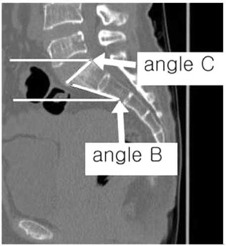
Angle B is angle between anterior cortical line of S1, 2 vertebral body and horizontal plane; Angle C is angle between superior aspect of S1 vertebral body and horizontal plane.

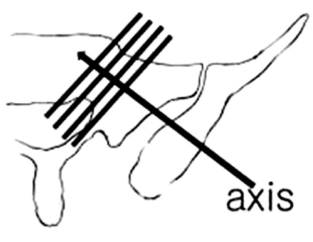
Fig. 5
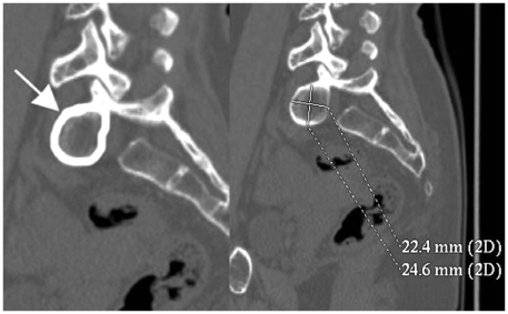
The example demonstrates how to measure Ap1Ax (area of S1 pedicle in pediculsr axis, arrow) and its long and short axis.
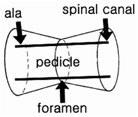
Fig. 6

The image of transparent inlet view and the illustration show alar indentation (maximal depth of anterior alar concavity) and alar length (length of anterior sacral ala).
Fig. 7
The schematic illustration shows safe zone in sacral pedicle. True safe zone in sacral pedicle is not obtainable in one cut image (The image is modified and cited from "The vestibule concepts"2)).
Fig. 8
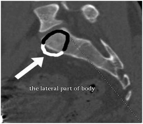
Anterior protrusion (white arrow) of safe zone (Ap1Ax) crosses the anterior sacral body after extension of Ap1Ax to the S1 body.
Fig. 9

Superior protrusion (white line) of safe zone (Ap1Ax) crosses the S1 superior end plate after extension of Ap1Ax to S1 body.
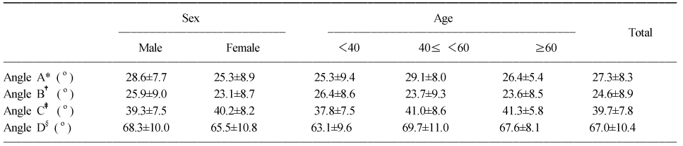
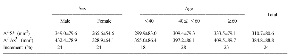
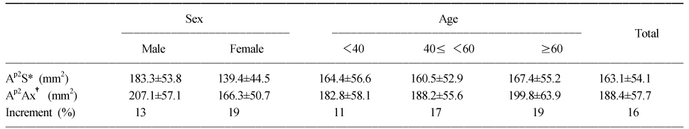
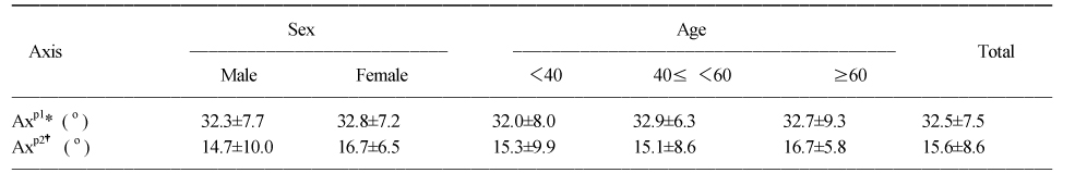
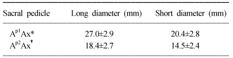
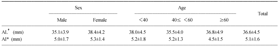
Figure & Data
REFERENCES
Citations
Citations to this article as recorded by 
- Percutaneous posterior transiliac plate versus iliosacral screw fixation for posterior fixation of Tile C-type pelvic fractures: a retrospective comparative study
Chul-Ho Kim, Jung Jae Kim, Ji Wan Kim
BMC Musculoskeletal Disorders.2022;[Epub] CrossRef - Measurement of Optimal Insertion Angle for Iliosacral Screw Fixation Using Three-Dimensional Computed Tomography Scans
Jung-Jae Kim, Chul-Young Jung, Jonathan G. Eastman, Hyoung-Keun Oh
Clinics in Orthopedic Surgery.2016; 8(2): 133. CrossRef
 Cite
CiteUpper Sacral Morphology Related to Iliosacral Screw Fixation in Korean
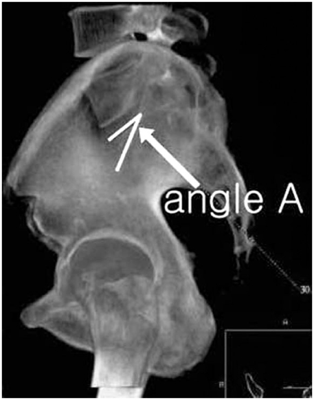

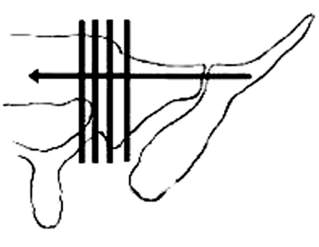


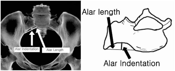


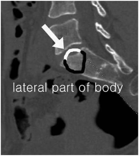
Fig. 1
Angle A is angle between superior aspect of S1 and iliac cortical density (ICD) line.
Fig. 2
Angle B is angle between anterior cortical line of S1, 2 vertebral body and horizontal plane; Angle C is angle between superior aspect of S1 vertebral body and horizontal plane.
Fig. 3
Cross line shows the cutting plane of Ap1S and Ap2S.
Fig. 4
Cross line shows cutting plane of Ap1Ax and Ap2Ax.
Fig. 5
The example demonstrates how to measure Ap1Ax (area of S1 pedicle in pediculsr axis, arrow) and its long and short axis.
Fig. 6
The image of transparent inlet view and the illustration show alar indentation (maximal depth of anterior alar concavity) and alar length (length of anterior sacral ala).
Fig. 7
The schematic illustration shows safe zone in sacral pedicle. True safe zone in sacral pedicle is not obtainable in one cut image (The image is modified and cited from "The vestibule concepts"2)).
Fig. 8
Anterior protrusion (white arrow) of safe zone (Ap1Ax) crosses the anterior sacral body after extension of Ap1Ax to the S1 body.
Fig. 9
Superior protrusion (white line) of safe zone (Ap1Ax) crosses the S1 superior end plate after extension of Ap1Ax to S1 body.
Fig. 1
Fig. 2
Fig. 3
Fig. 4
Fig. 5
Fig. 6
Fig. 7
Fig. 8
Fig. 9
Upper Sacral Morphology Related to Iliosacral Screw Fixation in Korean
The average angles of angle A, B, C, D classified by sex and age
*The angle between superior aspect of S1 body and iliac cortical density (ICD), †Angle between anterior cortical line of S1, 2 body and horizontal plane, ‡Angle between superior aspect of S1 body and horizontal plane, §The sum of angle A and C.
Area of S1 pedicle in sagittal and pedicular axis
*Area of S1 pedicle in sagittal plane, †Area of S1 pedicle in pedicular axis plane.
Area of S2 pedicle in sagittal and pedicular axis plane
*Area of S2 pedicle in sagittal plane, †Area of S2 pedicle in pedicular axis plane.
Axis of S1, 2 pedicle in axial view
*Axis of S1 pedicle, †Axis of S2 pedicle.
Diameters of pedicle in axis plane
*Area of S1 pedicle in pedicular axis plan, †Area of S2 pedicle in pedicular axis plan.
Alar indentation and alar length
*Alar indentation (maximal depth of anterior sacral ala), †Alar length (the length of anterior sacral ala).
Table 1
The average angles of angle A, B, C, D classified by sex and age
*The angle between superior aspect of S1 body and iliac cortical density (ICD), †Angle between anterior cortical line of S1, 2 body and horizontal plane, ‡Angle between superior aspect of S1 body and horizontal plane, §The sum of angle A and C.
Table 2
Area of S1 pedicle in sagittal and pedicular axis
*Area of S1 pedicle in sagittal plane, †Area of S1 pedicle in pedicular axis plane.
Table 3
Area of S2 pedicle in sagittal and pedicular axis plane
*Area of S2 pedicle in sagittal plane, †Area of S2 pedicle in pedicular axis plane.
Table 4
Axis of S1, 2 pedicle in axial view
*Axis of S1 pedicle, †Axis of S2 pedicle.
Table 5
Diameters of pedicle in axis plane
*Area of S1 pedicle in pedicular axis plan, †Area of S2 pedicle in pedicular axis plan.
Table 6
Alar indentation and alar length
*Alar indentation (maximal depth of anterior sacral ala), †Alar length (the length of anterior sacral ala).

