 E-submission
 TOTA
TOTA TOTS
TOTS
Articles
- Page Path
- HOME > J Musculoskelet Trauma > Volume 27(1); 2014 > Article
-
Original Article
- Radiological Assessment for Morphological Diversity of Distal Fibula
- Su-Young Bae, M.D., Ph.D., Jin Hee Yoo, M.D.
-
Journal of the Korean Fracture Society 2014;27(1):1-9.
DOI: https://doi.org/10.12671/jkfs.2014.27.1.1
Published online: January 17, 2014
Department of Orthopedic Surgery, Inje University Sanggye Paik Hospital, Seoul, Korea.
- Address reprint requests to: Su-Young Bae, M.D., Ph.D. Department of Orthopedic Surgery, Inje University Sanggye Paik Hospital, Dongil-ro 1342, Nowon-gu, Seoul 139-707, Korea. Tel: 82-2-950-1399, Fax: 82-2-950-1398, youngos@paik.ac.kr
• Received: May 14, 2013 • Revised: August 8, 2013 • Accepted: December 8, 2013
Copyright © 2014 The Korean Fracture Society. All rights reserved.
This is an Open Access article distributed under the terms of the Creative Commons Attribution Non-Commercial License (http://creativecommons.org/licenses/by-nc/3.0/) which permits unrestricted non-commercial use, distribution, and reproduction in any medium, provided the original work is properly cited.
- 774 Views
- 4 Download
Abstract
-
Purpose
- The purpose of this study is to determine whether the morphological consistency of distal fibula could be defined by measurement through radiological assessment as there was doubt regarding the adequacy of anatomical distal fibular plates.
-
Materials and Methods
- Plain radiographs and computed tomography (CT) images of 300 cases from 2009 to 2012 were reviewed. The distance from the lateral vertex to the tip of the distal fibula and to the lateral margin of the shaft was measured, respectively, in order to understand the shape of the lateral curve of the distal fibula on plain radiographs. The neutral ridge was defined as a point of the lateral ridge located in the center of the antero-posterior diameter and the distance from the tip of the distal fibula to the neutral ridge was measured for determining the shape of the ridge on CT images. The angle of the lateral and posterior surface of the fibular incisura at the level of the neutral ridge was also measured.
-
Results
- A statistically significant difference in the lateral vertex and margin of the fibular shaft on plain radiographs and distance from the tip of the distal fibula to the neutral ridge, angle of the fibular lateral surface on CT images was observed between male and female. The mean distance from the lateral vertex to the tip of distal fibula was 12.2±3.0 mm, to the lateral margin of the fibular shaft was 5.6±1.7 mm, distance from tip of the distal fibula to the neutral ridge was 54.9±6.4 mm, the fibular lateral surface angle was 52.2°±9.1°, and the fibular posterior surface angle was 32.5°±9.3°.
-
Conclusion
- Based on the various radiologic parameters, it was concluded that there was a wide morphological diversity of shape of lateral curve and fibular ridge.
- 1. Adachi N, Fukuhara K, Kobayashi T, Nakasa T, Ochi M. Morphologic variations of the fibular malleolar groove with recurrent dislocation of the peroneal tendons. Foot Ankle Int, 2009;30:540-544.ArticlePDF
- 2. Cole PA, Craft JA. Treatment of osteoporotic ankle fractures in the elderly: surgical strategies. Orthopedics, 2002;25:427-430.Article
- 3. Drake RL, Vogl W, Mitchell AWM. Gray's basic anatomy. Edinburgh: Churchill Livingstone; 2012.
- 4. Ebraheim NA, Taser F, Shafiq Q, Yeasting RA. Anatomical evaluation and clinical importance of the tibiofibular syndesmosis ligaments. Surg Radiol Anat, 2006;28:142-149.ArticlePDF
- 5. Hermans JJ, Beumer A, de Jong TA, Kleinrensink GJ. Anatomy of the distal tibiofibular syndesmosis in adults: a pictorial essay with a multimodality approach. J Anat, 2010;217:633-645.Article
- 6. Hess F, Sommer C. Minimally invasive plate osteosynthesis of the distal fibula with the locking compression plate: first experience of 20 cases. J Orthop Trauma, 2011;25:110-115.Article
- 7. Kim T, Ayturk UM, Haskell A, Miclau T, Puttlitz CM. Fixation of osteoporotic distal fibula fractures: a biomechanical comparison of locking versus conventional plates. J Foot Ankle Surg, 2007;46:2-6.Article
- 8. Krenk DE, Molinero KG, Mascarenhas L, Muffly MT, Altman GT. Results of minimally invasive distal fibular plate osteosynthesis. J Trauma, 2009;66:570-575.Article
- 9. Minihane KP, Lee C, Ahn C, Zhang LQ, Merk BR. Comparison of lateral locking plate and antiglide plate for fixation of distal fibular fractures in osteoporotic bone: a biomechanical study. J Orthop Trauma, 2006;20:562-566.Article
- 10. Ozbag D, Gumusalan Y, Uzel M, Cetinus E. Morphometrical features of the human malleolar groove. Foot Ankle Int, 2008;29:77-81.ArticlePDF
- 11. Schepers T, Van Lieshout EM, De Vries MR, Van der Elst M. Increased rates of wound complications with locking plates in distal fibular fractures. Injury, 2011;42:1125-1129.Article
- 12. Schulz AP, Reimers N, Wipf F, et al. Evidence based development of a novel lateral fibula plate (VariAx fibula) using a real ct bone data based optimization process during device development. Open Orthop J, 2012;6:1-7.ArticlePDF
- 13. Taşer F, Toker S, Kilinçoğlu V. Evaluation of morphometric characteristics of the fibular incisura on dry bones. Eklem Hastalik Cerrahisi, 2009;20:52-58.
- 14. van den Bekerom MP, Oostra RJ, Alvarez PG, van Dijk CN. The anatomy in relation to injury of the lateral collateral ligaments of the ankle: a current concepts review. Clin Anat, 2008;21:619-626.Article
- 15. Zahn RK, Frey S, Jakubietz RG, et al. A contoured locking plate for distal fibular fractures in osteoporotic bone: a biomechanical cadaver study. Injury, 2012;43:718-725.Article
REFERENCES
Fig. 1Lateral contour of the distal fibula was defined by measurement of distance from the distal tip (a) to the lateral vertex (b) in (A) and distance form vertex (d) to the lateral margin of the fibular shaft (c) in (B).
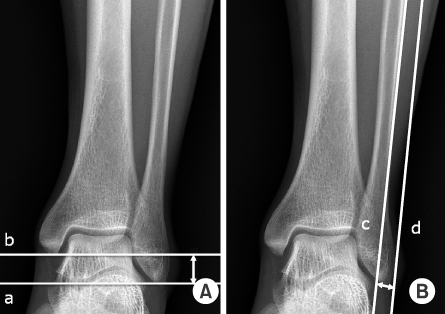
Fig. 2Shape of the distal fibula ridge was defined by measurement of the neutral ridge (A) and distance from the tip to the neutral ridge (B).

Fig. 3Shape of the distal fibula ridge was defined by measurement of the lateral surface angle, α (A) and posterior surface angle, β (B) at the level of the neutral ridge. *Line along the incisura fibularis at the level of the upper margin of the distal tibia-fibular joint.

Fig. 4Distance from the tip to the lateral vertex was distributed as follows. (A) Scattergram of a sample of 300 people divided into two groups of male and female. (B) Histogram of the percentage of the values.
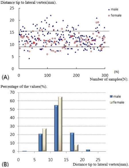
Fig. 5Lateral bulging was distributed as follows. (A) Scattergram of a sample of 300 people divided into two groups of male and female. (B) Histogram of the percentage of the values.
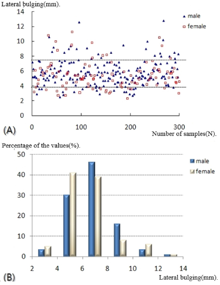
Fig. 6Distance from the tip to the neutral ridge was distributed as follows. (A) Scattergram of a sample of 300 people divided into two groups of male and female. (B) Histogram of the percentage of the values.

Fig. 7Lateral surface angle was distributed as follows. (A) Scattergram of a sample of 300 people divided into two groups of male and female. (B) Histogram of the percentage of the values.

Fig. 8Posterior surface angle was distributed as follows. (A) Scattergram of a sample of 300 people divided into two groups of male and female. (B) Histogram of the percentage of the values.

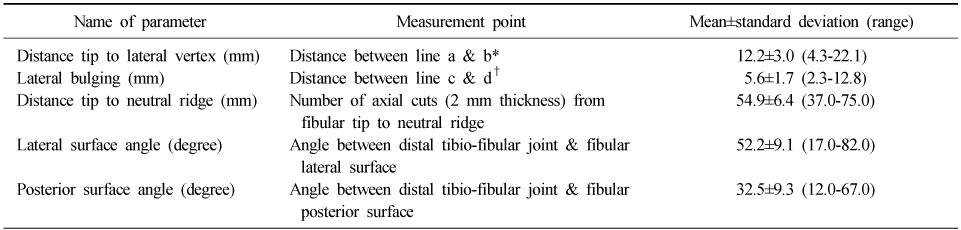
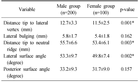
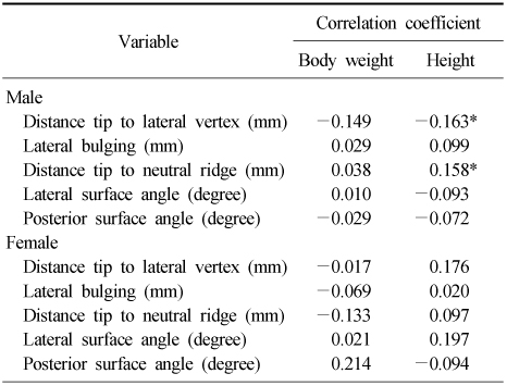
Figure & Data
REFERENCES
Citations
Citations to this article as recorded by 
 Cite
CiteRadiological Assessment for Morphological Diversity of Distal Fibula

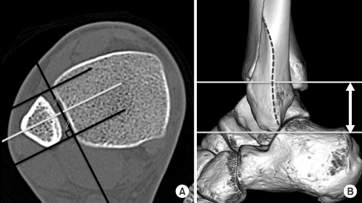
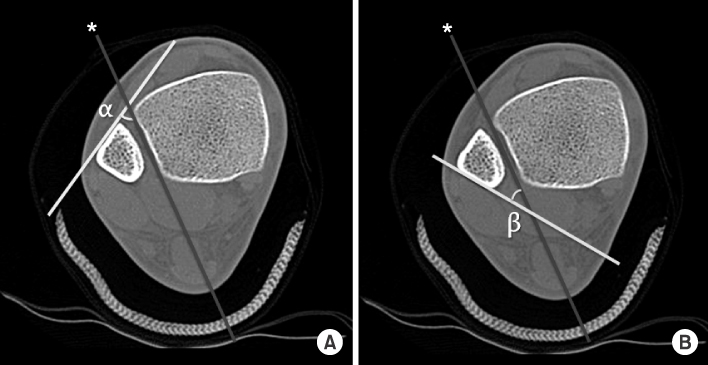


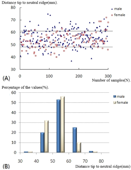
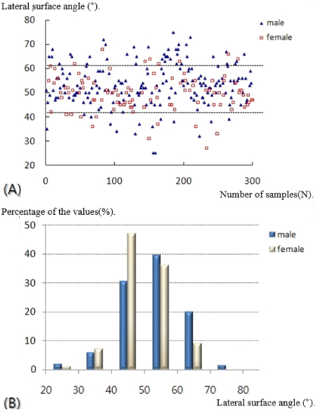
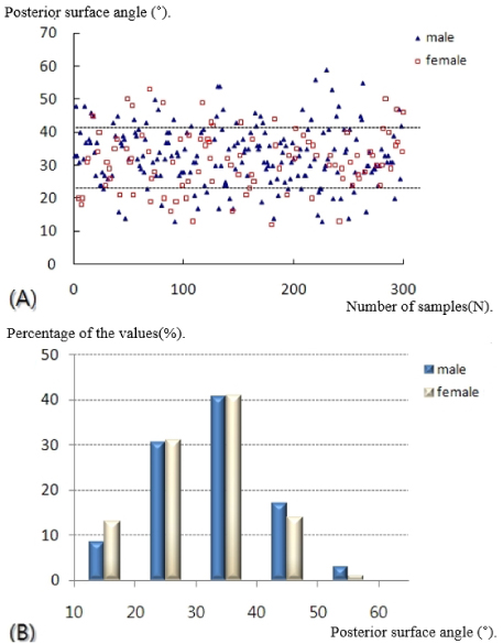
Fig. 1
Lateral contour of the distal fibula was defined by measurement of distance from the distal tip (a) to the lateral vertex (b) in (A) and distance form vertex (d) to the lateral margin of the fibular shaft (c) in (B).
Fig. 2
Shape of the distal fibula ridge was defined by measurement of the neutral ridge (A) and distance from the tip to the neutral ridge (B).
Fig. 3
Shape of the distal fibula ridge was defined by measurement of the lateral surface angle, α (A) and posterior surface angle, β (B) at the level of the neutral ridge. *Line along the incisura fibularis at the level of the upper margin of the distal tibia-fibular joint.
Fig. 4
Distance from the tip to the lateral vertex was distributed as follows. (A) Scattergram of a sample of 300 people divided into two groups of male and female. (B) Histogram of the percentage of the values.
Fig. 5
Lateral bulging was distributed as follows. (A) Scattergram of a sample of 300 people divided into two groups of male and female. (B) Histogram of the percentage of the values.
Fig. 6
Distance from the tip to the neutral ridge was distributed as follows. (A) Scattergram of a sample of 300 people divided into two groups of male and female. (B) Histogram of the percentage of the values.
Fig. 7
Lateral surface angle was distributed as follows. (A) Scattergram of a sample of 300 people divided into two groups of male and female. (B) Histogram of the percentage of the values.
Fig. 8
Posterior surface angle was distributed as follows. (A) Scattergram of a sample of 300 people divided into two groups of male and female. (B) Histogram of the percentage of the values.
Fig. 1
Fig. 2
Fig. 3
Fig. 4
Fig. 5
Fig. 6
Fig. 7
Fig. 8
Radiological Assessment for Morphological Diversity of Distal Fibula
Measurement Point and Parameters
*Draw the horizontal line on the tip of the distal fibula (a) and in parallel to the line through the lateral vertex (b) on plain radiographs.
†Draw the line along the margin of the fibular shaft (c) and in parallel to the line through the lateral vertex (d) on plain radiographs.
Comparison of the Radiographic Results between Two Groups
Values are presented as mean±standard deviation. *Significant at p-value<0.05.
Correlation Coefficient between Parameters of Fibular Shape and Body Size in Two Groups
*Significant at p-value<0.05.
Table 1
Measurement Point and Parameters
*Draw the horizontal line on the tip of the distal fibula (a) and in parallel to the line through the lateral vertex (b) on plain radiographs. †Draw the line along the margin of the fibular shaft (c) and in parallel to the line through the lateral vertex (d) on plain radiographs.
Table 2
Comparison of the Radiographic Results between Two Groups
Values are presented as mean±standard deviation. *Significant at p-value<0.05.
Table 3
Correlation Coefficient between Parameters of Fibular Shape and Body Size in Two Groups
*Significant at p-value<0.05.

