 E-submission
 TOTA
TOTA TOTS
TOTS
Articles
- Page Path
- HOME > J Musculoskelet Trauma > Volume 23(2); 2010 > Article
-
Original Article
- Effect of Fracture Gap on Biomechanical Stability of Compression Bone-Plate Fixation System after Bone Fracture Augmentation
- Duk-Young Jung, Ph.D., Sung-Jae Lee, Ph.D., Seon-Chil Kim, Ph.D., Jong-Keon Oh, M.D.
-
Journal of the Korean Fracture Society 2010;23(2):220-226.
DOI: https://doi.org/10.12671/jkfs.2010.23.2.220
Published online: April 30, 2010
*Senior Products Industrial Center, Busan Techno-park, Busan, Korea.
†Department of Biomedical Engineering, Inje University, Gimhae, Korea.
‡Department of Radiologic Technology, Daegu Health College, Daegu, Korea.
§Department of Orthopedic Surgery, Korea University College of Medicine, Seoul, Korea.
- Address reprint requests to: Jong-Keon Oh, M.D. Department of Orthopedic Surgery, Korea University College of Medicine, 80, Guro-dong, Guro-gu, Seoul 152-703, Korea. Tel: 82-2-2626-3088, Fax: 82-2-2626-1164, jkoh@korea.ac.kr
• Received: October 7, 2009 • Revised: December 10, 2009 • Accepted: January 28, 2010
Copyright © 2010 The Korean Fracture Society
- 1,234 Views
- 5 Download
Abstract
-
Purpose
- The goal of this study using the biomechanical test was to evaluate the mechanical stability of the bone-plate fixation system according to changes of the fracture gap sizes and widths.
-
Materials and Methods
- For mechanical test, four types with different fracture models simulating the clinical situations were constructed depending on the gap size (FGS, mm) and the gap width (FGW, %) at the fracture site: 0 mm/0%, 1 mm/100%, 4 mm/100%, 4 mm/50%. For analyzing the effects of fracture gap on the biomechanical stability of the bone-plate fixation system, 4-point bending test was performed under all same conditions.
-
Results
- It was found that the fracture gap sizes of 1 and 4 mm decreased mechanical stiffness by about 50~60% or more. Furthermore, even without fracture gap size, 50% or more fracture gap width considerably decreased mechanical stiffness and suggested the possibility of plate damage through strain results.
-
Conclusion
- Our findings suggested that at least 50% contact of the fracture faces in a fracture surgery would be maintained to increase the mechanical stability of the bone-plate fixation system.
- 1. Baumgaertel F, Buhl M, Rahn BA. Fracture healing in biological plate osteosynthesis. Injury, 1998;29:Suppl 3. C3-C6.Article
- 2. Cordey J, Borgeaud M, Perren SM. Force transfer between the plate and the bone: relative importance of the bending stiffness of the screws and the friction between plate and bone. Injury, 2000;31:Suppl 3. C21-C28.Article
- 3. Frigg R. Locking compression plate (LCP). An osteosynthesis plate based on the Dynamic Compression Plate and Point Contact Fixator (PC-Fix). Injury, 2001;32:Suppl 2. 63-66.Article
- 4. Gardner MJ, Brophy RH, Campbell D, et al. The mechanical behavior of locking compression plates compared with dynamic compression plates in a cadaver radius model. J Orthop Trauma, 2005;19:597-603.Article
- 5. Gautier E, Perren SM, Cordey J. Effect of plate position relative to bending direction on the rigidity of a plate ostosynthesis. A theoretical analysis. Injury, 2000;31:Suppl 3. C14-C20.
- 6. Korner J, Diederichs G, Arzdorf M, et al. A biomechanical evaluation of methods of distal humerus fracture fixation using locking compression plate versus conventional reconstruction plates. J Orthop Trauma, 2004;18:286-293.
- 7. Fulkerson E, Egol KA, Kubiak EN, Liporace F, Kummer FJ, Koval KJ. Fixation of diaphyseal fractures with segmental defects: a biomechanical comparison of locked and conventional plating techniques. J Trauma, 2006;60:830-835.
- 8. Perren SM. Evolution of the internal fixation of long bone fracture. J Bone Joint Surg Br, 2002;84:1093-1110.
- 9. Ramakrishna K, Shidhar I, Sivashanker S, Khong KS, Ghista DN. Design of fracture fixation plate for necessary and sufficient bone stress shielding. JSME International Journal Series C, 2004;47:1086-1094.Article
- 10. Sommer C, Gautier E, Müller M, Helfet DL, Wagner M. First clinical results of the locking compression plate (LCP). Injury, 2003;34:Suppl 2. B43-B54.Article
- 11. Stoffel K, Dieter U, Stachowiak G, Gächter A, Kuster MS. Biomechanical testing of the LCP - how can stability in locked internal fixators be controlled? Injury, 2003;34:Suppl 2. B11-B19.Article
- 12. Stoffel K, Stachowiak G, Forster T, Gächter A, Kuster M. Oblique screws at the plate ends increase the fixation strength in synthetic bone test medium. J Orthop Trauma, 2004;18:611-616.Article
REFERENCES
Figure 1The LC-DCP bone fixation system and the epoxy pipe represented as a bone (A) and specimen configurations (B) for the fracture gap sizes & width (mm/%).

Figure 2Mechanical experiment through 4-pont bending test (A→B→D→C) with LC-DCP bone- plate fixation system.
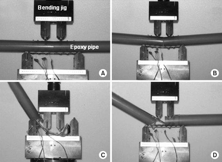
Figure 3Determination of the initial and final bending stiffness (Nm/°) with the bending moment (Nm)-bending angle (°) curve.

Figure 4Comparison of bending moments according to the fracture gap sizes and widths on the LC-DCP fixation system.
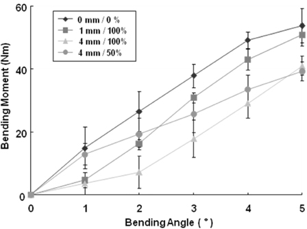
Figure 5Comparison of the initial and final bending stiffness (Nm/°) according to the fracture gap sizes and widths of LC-DCP: *indicates significant difference compared with 0 mm/0% model in the initial stiffness.

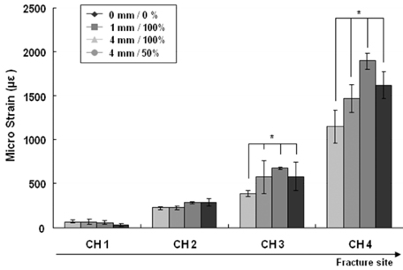
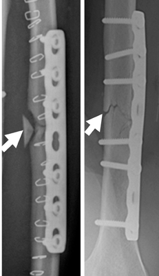
Figure & Data
REFERENCES
Citations
Citations to this article as recorded by 
 Cite
CiteEffect of Fracture Gap on Biomechanical Stability of Compression Bone-Plate Fixation System after Bone Fracture Augmentation
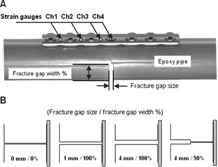

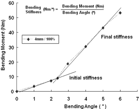

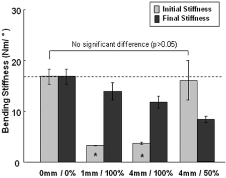


Figure 1
The LC-DCP bone fixation system and the epoxy pipe represented as a bone (A) and specimen configurations (B) for the fracture gap sizes & width (mm/%).
Figure 2
Mechanical experiment through 4-pont bending test (A→B→D→C) with LC-DCP bone- plate fixation system.
Figure 3
Determination of the initial and final bending stiffness (Nm/°) with the bending moment (Nm)-bending angle (°) curve.
Figure 4
Comparison of bending moments according to the fracture gap sizes and widths on the LC-DCP fixation system.
Figure 5
Comparison of the initial and final bending stiffness (Nm/°) according to the fracture gap sizes and widths of LC-DCP: *indicates significant difference compared with 0 mm/0% model in the initial stiffness.
Figure 6
Comparison of the micro strains (µε) through the four channels (Ch1~Ch4) according to the fracture gap sizes and widths on LC-DCP (p<0.01): *indicates significant difference compared with 0 mm/0% model in the initial stiffness.
Figure 7
The facture gap shapes after compression plating with bone-plate fixation system: the white arrows indicate bone fracture position.
Figure 1
Figure 2
Figure 3
Figure 4
Figure 5
Figure 6
Figure 7
Effect of Fracture Gap on Biomechanical Stability of Compression Bone-Plate Fixation System after Bone Fracture Augmentation

