 E-submission
 TOTA
TOTA TOTS
TOTS
Articles
- Page Path
- HOME > J Musculoskelet Trauma > Volume 30(3); 2017 > Article
-
Review Article
- Clinical and Radiological Analysis of Angular Deformity of Lower Extremities
- Changhoon Jeong, M.D., Jong Ho Noh, M.D.
-
Journal of the Korean Fracture Society 2017;30(3):156-166.
DOI: https://doi.org/10.12671/jkfs.2017.30.3.156
Published online: January 10, 2017
Department of Orthopedic Surgery, Bucheon St. Mary's Hospital, College of Medicine, The Catholic University of Korea, Bucheon, Korea
- Correspondence to: Changhoon Jeong, M.D. Department of Orthopedic Surgery, Bucheon St. Mary's Hospital, College of Medicine, The Catholic University of Korea, 327 Sosa-ro, Bucheon 14647, Korea Tel: +82-32-340-7089 Fax: +82-32-340-2671 E-mail: changhoonj@gmail.com
Copyright © 2017 The Korean Fracture Society
This is an Open Access article distributed under the terms of the Creative Commons Attribution Non-Commercial License (http://creativecommons.org/licenses/by-nc/4.0) which permits unrestricted non-commercial use, distribution, and reproduction in any medium, provided the original work is properly cited.
- 7,550 Views
- 231 Download
- 6 Crossref
Abstract
- The alignment of lower extremities is an important consideration in many clinical situations, including fracture reduction, high tibia osteotomy, total knee arthroplasty, and deformity correction. Malalignment of lower extremities is not only a simple cosmetic problem, but it can also produce pain, limp, and early degenerative arthritis. An assessment of lower extremity alignment, including its location and magnitude of deformity, can be achieved via Malalignment test and mal-orientation test, using a lower extremity standing full-length radiography. Proper evaluation allows the surgeon to determine an effective treatment plan for deformity correction.
Fig. 1.Nomenclature of the frontal plane joint orientation angle relative to the mechanical axis (A) and anatomic axis (B). (C) Nomenclature of the sagittal plane joint orientation angle relative to the anatomic axis. LPFA: lateral proximal femoral angle, mLDFA: mechanical lateral distal femoral angle, MPTA: medial proximal tibial angle, LDTA: lateral distal tibial angle, MPFA: medial proximal femoral angle, MNSA: medical neck shaft angle, LDFA: lateral distal femoral angle, JLCA: joint line convergence angle, PPFA: posterior proximal femoral angle, ANSA: anatomic neck shaft angle, PDFA: posterior distal femoral angle, PPTA: posterior proximal tibial angle, ADTA: anterior distal tibial angle.

Fig. 2.Anatomic axis to joint center distance (aJCD) of the hip joint of the hip (A) and tibia (B). Bold line: anatomic axis, Dot line: joint center point. d: distance.

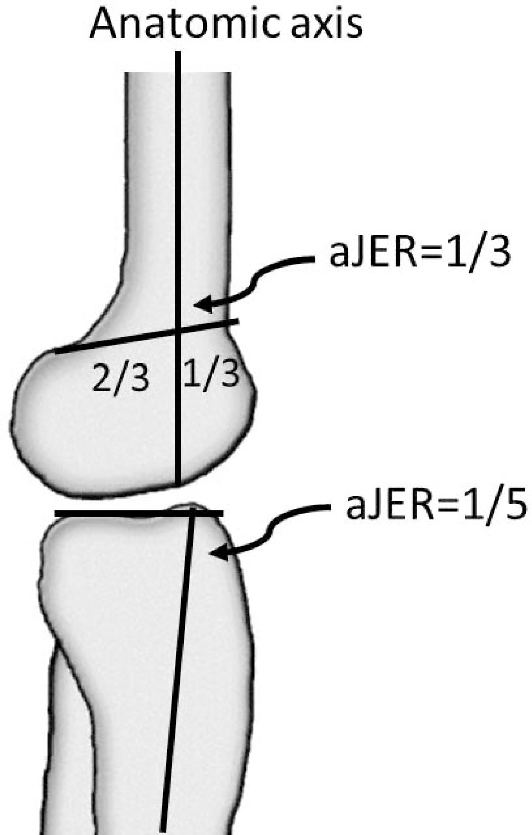
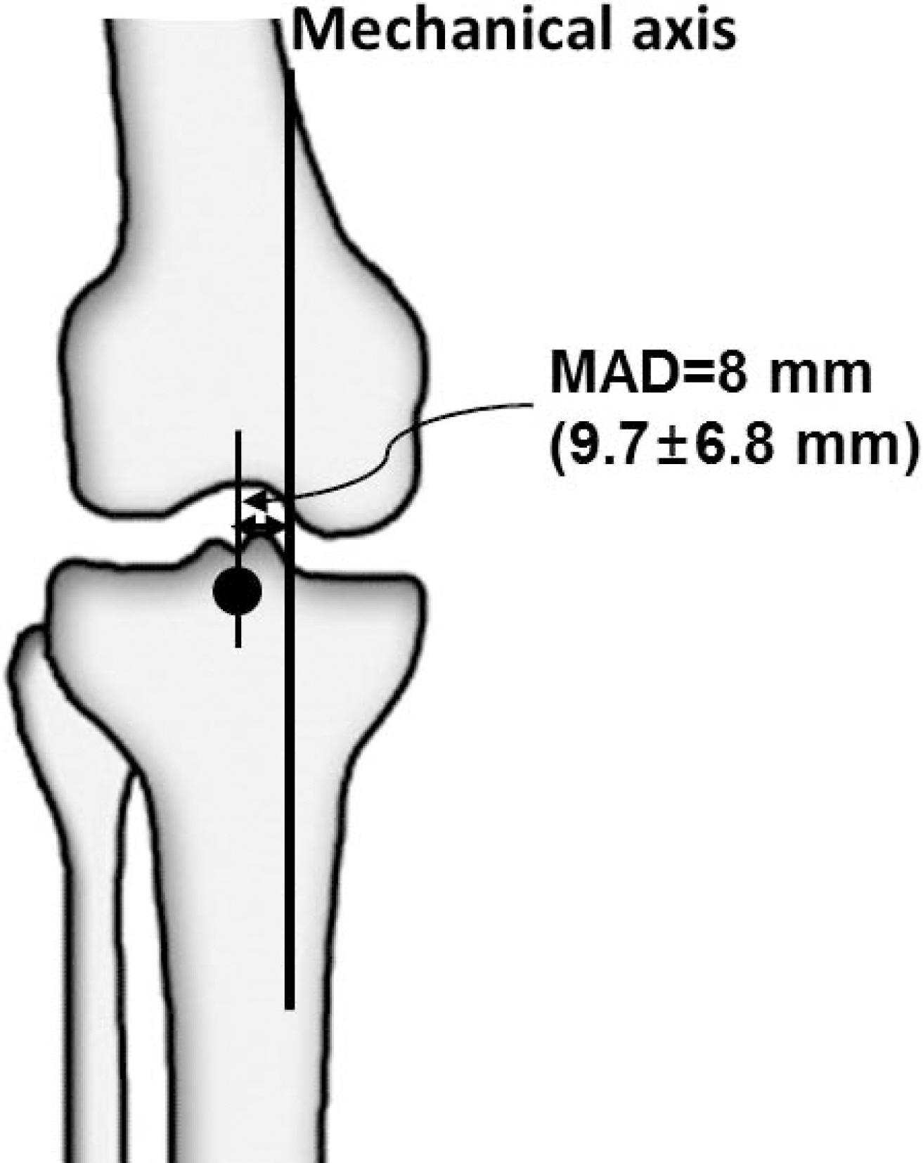
Fig. 5.(A) If center of rotation of angulation (CORA) lies at the point of obvious deformity apex in the bone and the joint orientations are normal, the deformity is uniapical. (B) If CORA lies outside the point of obvious deformity apex or either joint orientation is abnormal, a second CORA exists in that plane and the deformity is multiapical or a translational deformity exists in that plane. (C) When the CORA lies outside the boundaries of the involved bone, a multiapical deformity is likely to be present.
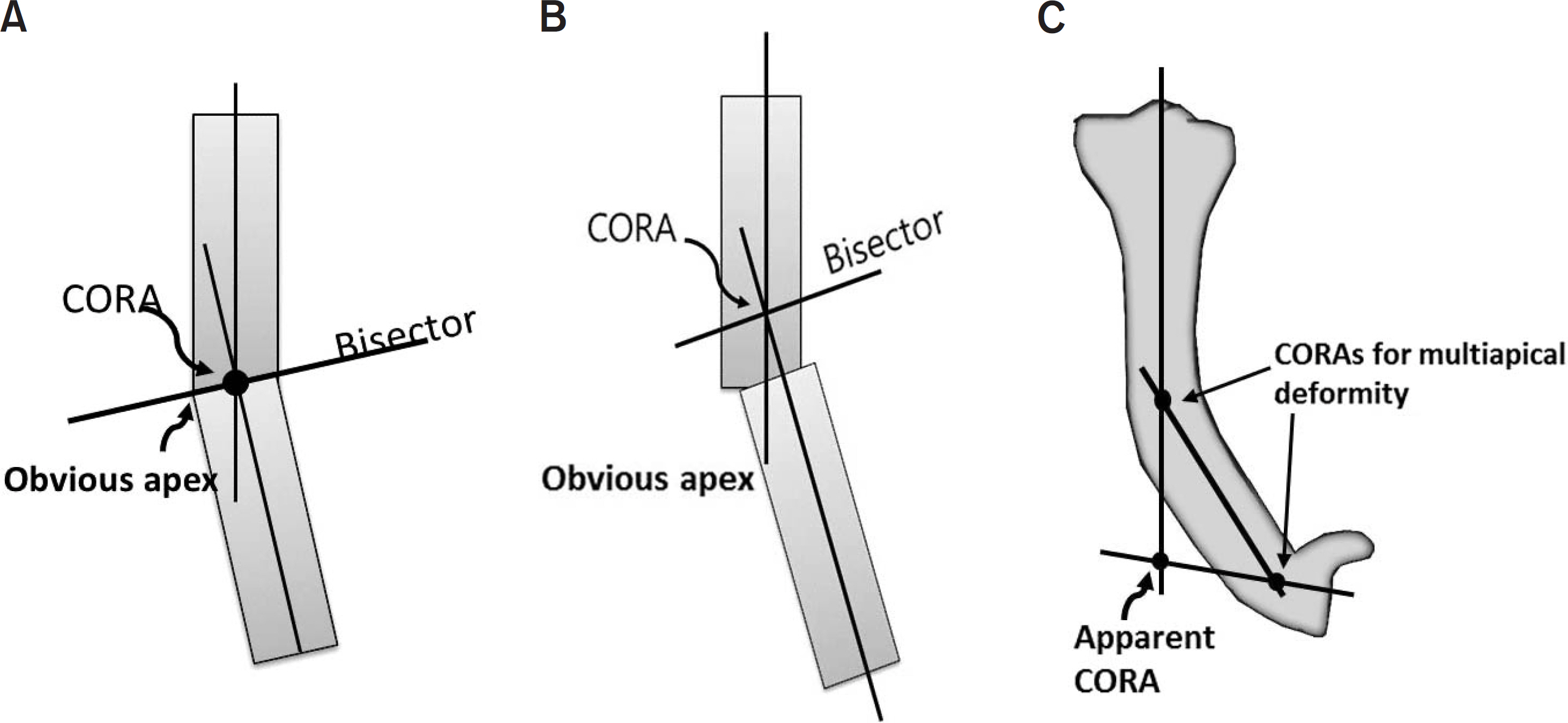
Fig. 6.The Malalignment test is to identify the sources of mechanical axis deviation. Step 0 is to draw the mechanical axis; Step 1 is to measure the mLDFA; Step 2 is to measure the MPTA; Step 3 is to measure the JLCA; Step 4 is to measure the joint center distance; and Step 5 is to identify the joint surface Malalignment. mLDFA: mechanical lateral distal femoral angle, MPTA: medial proximal tibial angle, JLCA: joint line convergence angle, JCP: joint center point.

Fig. 7.The standing lateral full length radiography of lower extremity shows 15° of hyperextension (HE) of the knee joint and 120° of PDFA, which is 36° recurvatum of the distal femur. Therefore, there is also 21° of knee joint flexion contracture and genu recurvatum. PDFA: posterior distal femoral angle, PPTA: posterior proximal tibial angle.

Fig. 8.Analysis of uniapical deformity of the tibia using the mechanical axis: Draw the mechanical axis and measure MAD (A). Draw the mechanical axis of the femur and tibia. Measure mLDFA and MPTA (B). If MPTA is outside the normal range, the mechanical axis of the femur is extended distally as a mechanical axis line when mLDFA is within normal range. Draw the mechanical axis of distal tibia from the center of the ankle parallel to the diaphysis of the tibia and measure LDTA. If LDTA is within normal range, mark the CORA and measure the magnitude of angulation (C). MAD: mechanical axis deviation, mLDFA: mechanical lateral distal femoral angle, MPTA: medial proximal tibial angle, LDTA: lateral distal tibial angle, CORA: center of rotation of angulation, Mag: magnitude of deformity.
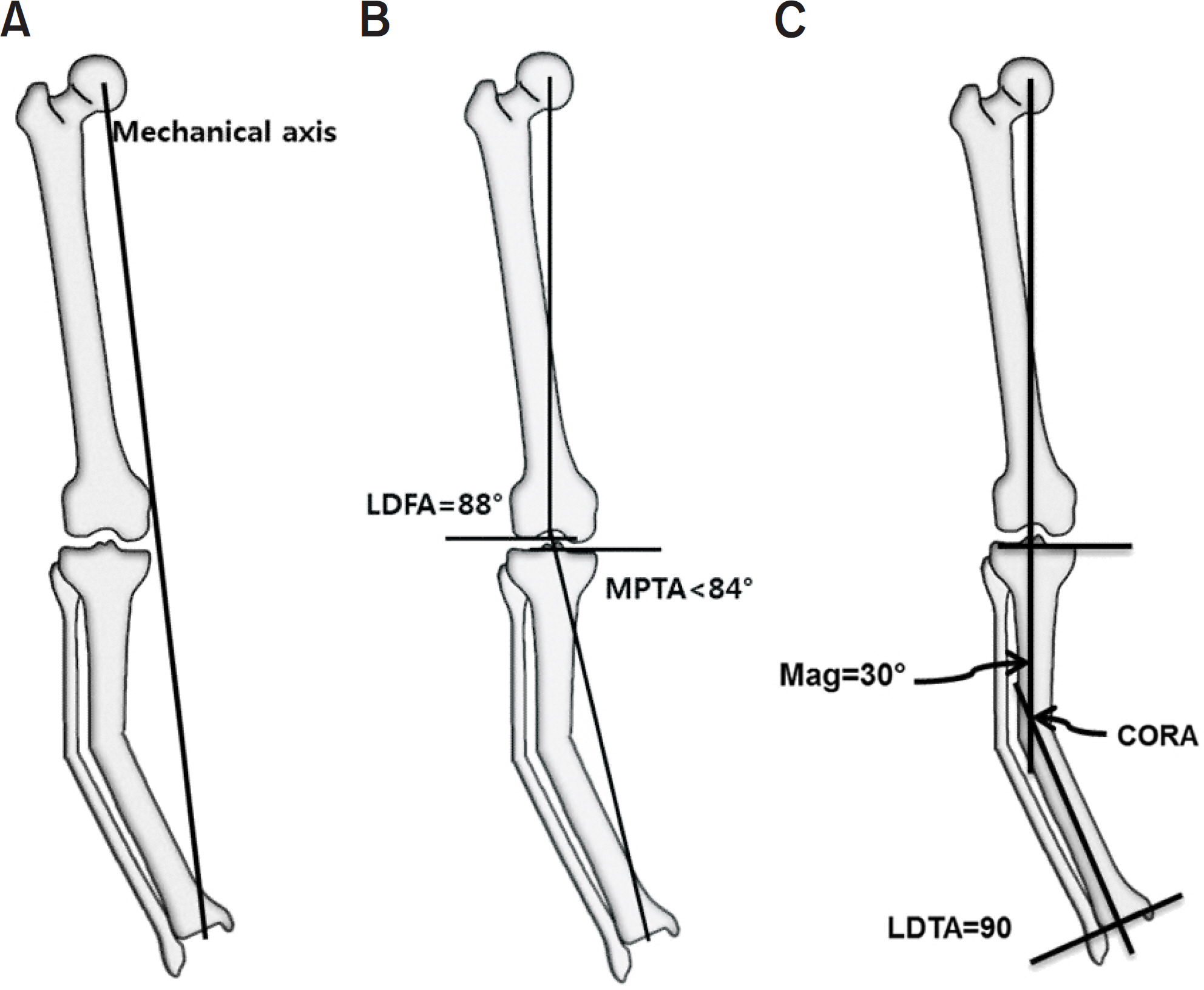
Table 1.Normal Values for Joint Orientation Angles in Lower Extremity
Table 2.Clinical Signs and Symptoms Associated with Sagittal Plane Deformity of Lower Extremity21)
- 1. Beals RK, Stanley G. Surgical correction of bowlegs in achondroplasia. J Pediatr Orthop B, 14:245-249. 2005.
- 2. Cusick BD, Stuberg WA. Assessment of lower-extremity alignment in the transverse plane: implications for management of children with neuromotor dysfunction. Phys Ther, 72:3-15. 1992.
- 3. Song HR, Soma Raju VV, Kumar S, et al. Deformity correction by external fixation and/or intramedullary nailing in hypophosphatemic rickets. Acta Orthop, 77:307-314. 2006.
- 4. Tetsworth K, Paley D. Malalignment and degenerative arthropathy. Orthop Clin North Am, 25:367-377. 1994.
- 5. Felson DT, Niu J, Gross KD, et al. Valgus malalignment is a risk factor for lateral knee osteoarthritis incidence and progression: findings from the multicenter osteoarthritis study and the osteoarthritis initiative. Arthritis Rheum, 65:355-362. 2013.
- 6. Moreland JR, Bassett LW, Hanker GJ. Radiographic analysis of the axial alignment of the lower extremity. J Bone Joint Surg Am, 69:745-749. 1987.
- 7. Paley D, Herzenberg JE, Tetsworth K, McKie J, Bhave A. Deformity planning for frontal and sagittal plane corrective osteotomies. Orthop Clin North Am, 25:425-465. 1994.
- 8. Chao EY, Neluheni EV, Hsu RW, Paley D. Biomechanics of malalignment. Orthop Clin North Am, 25:379-386. 1994.
- 9. Cooke TD, Li J, Scudamore RA. Radiographic assessment of bony contributions to knee deformity. Orthop Clin North Am, 25:387-393. 1994.
- 10. Yoshioka Y, Siu D, Cooke TD. The anatomy and functional axes of the femur. J Bone Joint Surg Am, 69:873-880. 1987.
- 11. Brinker MR, O'Connor DP. Principles of malunions. In: Court-Brown CM, Heckman JD, McQueen MM, Ricci WM, III PT, editors. Rockwood and Green's fractures in adults. 8th ed.Philadelphia, Wolters Kluwer Health: 869–894; 2015.
- 12. Lesiak AC, Vosseller JT, Rozbruch SR. Osteotomy, arthrodesis, and arthroplasty for complex multiapical deformity of the leg. HSS J, 8:304-308. 2012.
- 13. Krettek C, Miclau T, Grün O, Schandelmaier P, Tscherne H. Intraoperative control of axes, rotation and length in femoral and tibial fractures. Technical note. Injury, 29 Suppl, 3:C29-C39. 1998.
- 14. Sheehy L, Cooke TD, McLean L, Culham E. Standardized standing pelvis-to-floor photographs for the assessment of lower-extremity alignment. Osteoarthr Cartil, 23:379-382. 2015.
- 15. Wu CC. Is clinical measurement of anatomic axis of the femur adequate? Acta Orthop, 1–4:2017.
- 16. Hollister AM, Jatana S, Singh AK, Sullivan WW, Lupichuk AG. The axes of rotation of the knee. Clin Orthop Relat Res, 290:259-268. 1993.
- 17. Wright JG, Treble N, Feinstein AR. Measurement of lower limb alignment using long radiographs. J Bone Joint Surg Br, 73:721-723. 1991.
- 18. Paley D. Principles of deformity correction. 3rd ed.Berlin; Springer: 2005.
- 19. Holme TJ, Henckel J, Hartshorn K, Cobb JP, Hart AJ. Computed tomography scanogram compared to long leg radiograph for determining axial knee alignment. Acta Orthop, 86:440-443. 2015.
- 20. Sabharwal S, Zhao C. Assessment of lower limb alignment: supine fluoroscopy compared with a standing full-length radiograph. J Bone Joint Surg Am, 90:43-51. 2008.
- 21. Paley D, Tetsworth K. Mechanical axis deviation of the lower limbs. Preoperative planning of uniapical angular deformities of the tibia or femur. Clin Orthop Relat Res, 280:48-64. 1992.
- 22. Paley D. Principles of deformity correction. Berlin: Springer; p. 1632005.
- 23. Paley D, Chaudray M, Pirone AM, Lentz P, Kautz D. Treatment of malunions and mal-nonunions of the femur and tibia by detailed preoperative planning and the Ilizarov techniques. Orthop Clin North Am, 21:667-691. 1990.
REFERENCES
Figure & Data
REFERENCES
Citations
Citations to this article as recorded by 
- A deep learning approach for fully automated measurements of lower extremity alignment in radiographic images
Ki-Ryum Moon, Byoung-Dai Lee, Mu Sook Lee
Scientific Reports.2023;[Epub] CrossRef - Comparison of Lower-Limb Alignment in Patients with Advanced Knee Osteoarthritis: EOS Biplanar Stereoradiography versus Conventional Scanography
Hyeong-Uk Choi, Du-Han Kim, Si-Wook Lee, Byung-Chan Choi, Ki-Cheor Bae
Clinics in Orthopedic Surgery.2022; 14(3): 370. CrossRef - Prevalence of proximal tibia vara in Indonesian population with knee osteoarthritis
John Christian Parsaoran Butarbutar, Tommy Mandagi, Lasa Dhakka Siahaan, Earlene Tasya Suginawan, Elson, Irvan
Journal of Clinical Orthopaedics and Trauma.2022; 29: 101871. CrossRef - Morphometric parameters of the proximal femoral epiphysis and their effect on the hip joint
Jovan Varda, Vanja Valčić, Valentina Blagojević
Medicinski podmladak.2022; 73(2): 28. CrossRef - Factors related to femoral bowing among Korean female farmers: a cross-sectional study
Sangyoon Do, Chul Gab Lee, Dong Hwi Kim, GwangChul Lee, Kweon Young Kim, So Yeon Ryu, Hansoo Song
Annals of Occupational and Environmental Medicine.2020;[Epub] CrossRef - Effectiveness Evaluation of Scanogram Using Longbone Detector
Su-han Jang, Ji-eun Heo
Journal of Radiological Science and Technology.2020; 43(4): 235. CrossRef
 Cite
CiteClinical and Radiological Analysis of Angular Deformity of Lower Extremities
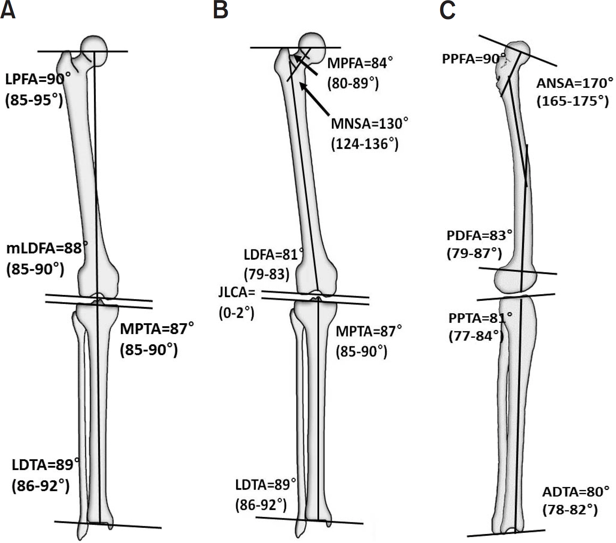
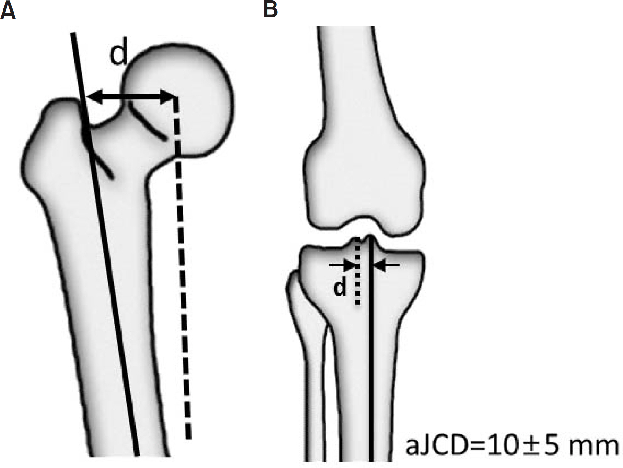


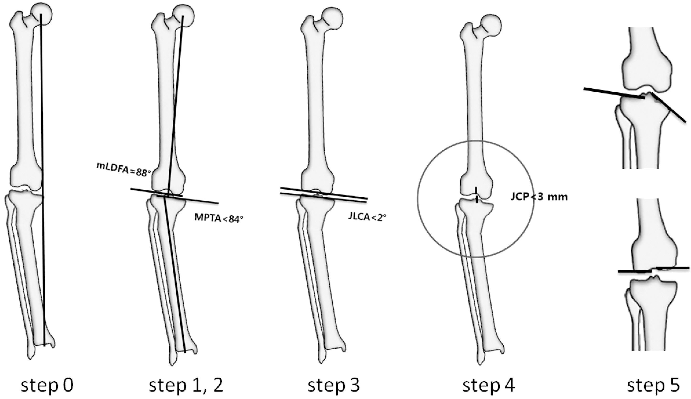
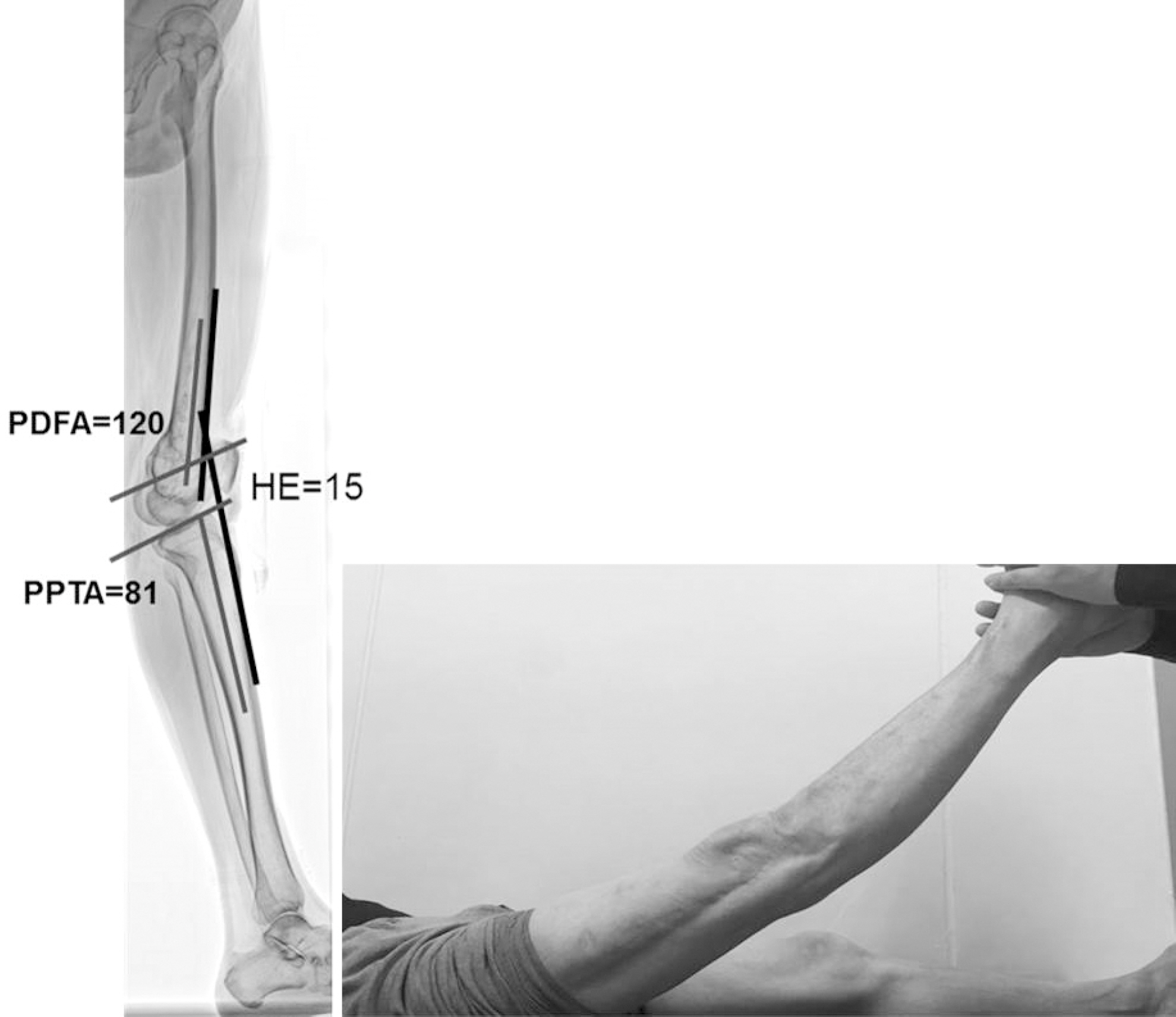

Fig. 1. Nomenclature of the frontal plane joint orientation angle relative to the mechanical axis (A) and anatomic axis (B). (C) Nomenclature of the sagittal plane joint orientation angle relative to the anatomic axis. LPFA: lateral proximal femoral angle, mLDFA: mechanical lateral distal femoral angle, MPTA: medial proximal tibial angle, LDTA: lateral distal tibial angle, MPFA: medial proximal femoral angle, MNSA: medical neck shaft angle, LDFA: lateral distal femoral angle, JLCA: joint line convergence angle, PPFA: posterior proximal femoral angle, ANSA: anatomic neck shaft angle, PDFA: posterior distal femoral angle, PPTA: posterior proximal tibial angle, ADTA: anterior distal tibial angle.
Fig. 2. Anatomic axis to joint center distance (aJCD) of the hip joint of the hip (A) and tibia (B). Bold line: anatomic axis, Dot line: joint center point. d: distance.
Fig. 3. Anatomic axis to joint edge ratio (aJER) of the distal femur and proximal tibia.
Fig. 4. Mechanical axis deviation (MAD).
Fig. 5. (A) If center of rotation of angulation (CORA) lies at the point of obvious deformity apex in the bone and the joint orientations are normal, the deformity is uniapical. (B) If CORA lies outside the point of obvious deformity apex or either joint orientation is abnormal, a second CORA exists in that plane and the deformity is multiapical or a translational deformity exists in that plane. (C) When the CORA lies outside the boundaries of the involved bone, a multiapical deformity is likely to be present.
Fig. 6. The Malalignment test is to identify the sources of mechanical axis deviation. Step 0 is to draw the mechanical axis; Step 1 is to measure the mLDFA; Step 2 is to measure the MPTA; Step 3 is to measure the JLCA; Step 4 is to measure the joint center distance; and Step 5 is to identify the joint surface Malalignment. mLDFA: mechanical lateral distal femoral angle, MPTA: medial proximal tibial angle, JLCA: joint line convergence angle, JCP: joint center point.
Fig. 7. The standing lateral full length radiography of lower extremity shows 15° of hyperextension (HE) of the knee joint and 120° of PDFA, which is 36° recurvatum of the distal femur. Therefore, there is also 21° of knee joint flexion contracture and genu recurvatum. PDFA: posterior distal femoral angle, PPTA: posterior proximal tibial angle.
Fig. 8. Analysis of uniapical deformity of the tibia using the mechanical axis: Draw the mechanical axis and measure MAD (A). Draw the mechanical axis of the femur and tibia. Measure mLDFA and MPTA (B). If MPTA is outside the normal range, the mechanical axis of the femur is extended distally as a mechanical axis line when mLDFA is within normal range. Draw the mechanical axis of distal tibia from the center of the ankle parallel to the diaphysis of the tibia and measure LDTA. If LDTA is within normal range, mark the CORA and measure the magnitude of angulation (C). MAD: mechanical axis deviation, mLDFA: mechanical lateral distal femoral angle, MPTA: medial proximal tibial angle, LDTA: lateral distal tibial angle, CORA: center of rotation of angulation, Mag: magnitude of deformity.
Fig. 1.
Fig. 2.
Fig. 3.
Fig. 4.
Fig. 5.
Fig. 6.
Fig. 7.
Fig. 8.
Clinical and Radiological Analysis of Angular Deformity of Lower Extremities
Normal Values for Joint Orientation Angles in Lower Extremity
| Bone-Plane | Component | Mean value (°) | Normal range (°) | |
|---|---|---|---|---|
| Femur-Frontal | ||||
| Anatomic medial proximal femoral angle (aMPFA) | Anatomic axis | Trochanter-head line | 84 | 80–89 |
| Mechanical lateral proximal femoral angle (mLPFA) | Mechanical axis | Trochanter-head line | 90 | 85–95 |
| Neck shaft angle (NSA) | Anatomic axis | Femoral neck line | 130 | 124–136 |
| Anatomic lateral distal femoral angle (aLDFA) | Anatomic axis | Distal femoral joint orientation line | 81 | 79–83 |
| Mechanical lateral distal femoral angle (mLDFA) | Mechanical axis | Distal femoral joint orientation line | 88 | 85–90 |
| Femur-Sagittal | ||||
| Posterior distal femoral angle (PDFA) | Mid-diaphyseal line | Sagittal distal femoral joint orientation line | 83 | 79–87 |
| Tibial-Frontal | ||||
| Medial proximal tibial angle (MPTA) | Mechanical axis | Proximal tibial joint orientation line | 87 | 85–90 |
| Lateral distal tibial angle (LDTA) | Mechanical axis | Distal tibial joint orientation line | 89 | 88–92 |
| Tibial-Sagittal | ||||
| Posterior proximal tibial angle (PPTA) | Mid-diaphyseal line | Sagittal proximal tibial joint orientation line | 81 | 77–84 |
| Anterior distal tibial angle (ADTA) | Mid-diaphyseal line | Sagittal distal tibial joint orientation line | 80 | 78–82 |
Clinical Signs and Symptoms Associated with Sagittal Plane Deformity of Lower Extremity21)
| Sagittal plane deformity | Clinical symptom & sign |
|---|---|
| Proximal femur flexion deformity | Hyperlordosis of spine |
| Proximal femur extension deformity | Loss of hip flexion |
| Distal femur procurvatum | Flexion deformity and stretching of posterior knee joint capsule |
| Distal femur recurvatum | Loss of flexion |
| Proximal tibia recurvatum | Chondromalacia patella |
| Proximal tibia procurvatum | Knee flexion deformiry, chondromalacia & pain |
| Distal tibia recurvatum | Late degenerative joint disease |
| Distal tibia procurvatum | Anterior impingement syndrome |
Table 1. Normal Values for Joint Orientation Angles in Lower Extremity
Table 2. Clinical Signs and Symptoms Associated with Sagittal Plane Deformity of Lower Extremity21)

