 E-submission
 TOTA
TOTA TOTS
TOTS
Search
- Page Path
- HOME > Search
Original Articles
- Computed tomography plane reformatting to reduce projection error in measuring Pauwels angle of femoral neck fractures: a cross-sectional study
- Gyu Min Kong, Jae-Young Lim, Se-Lin Jeong, Gu-Hee Jung
- J Musculoskelet Trauma 2026;39(1):38-47. Published online January 25, 2026
- DOI: https://doi.org/10.12671/jmt.2025.00038
-
 Abstract
 PDF
PDF - Objectives
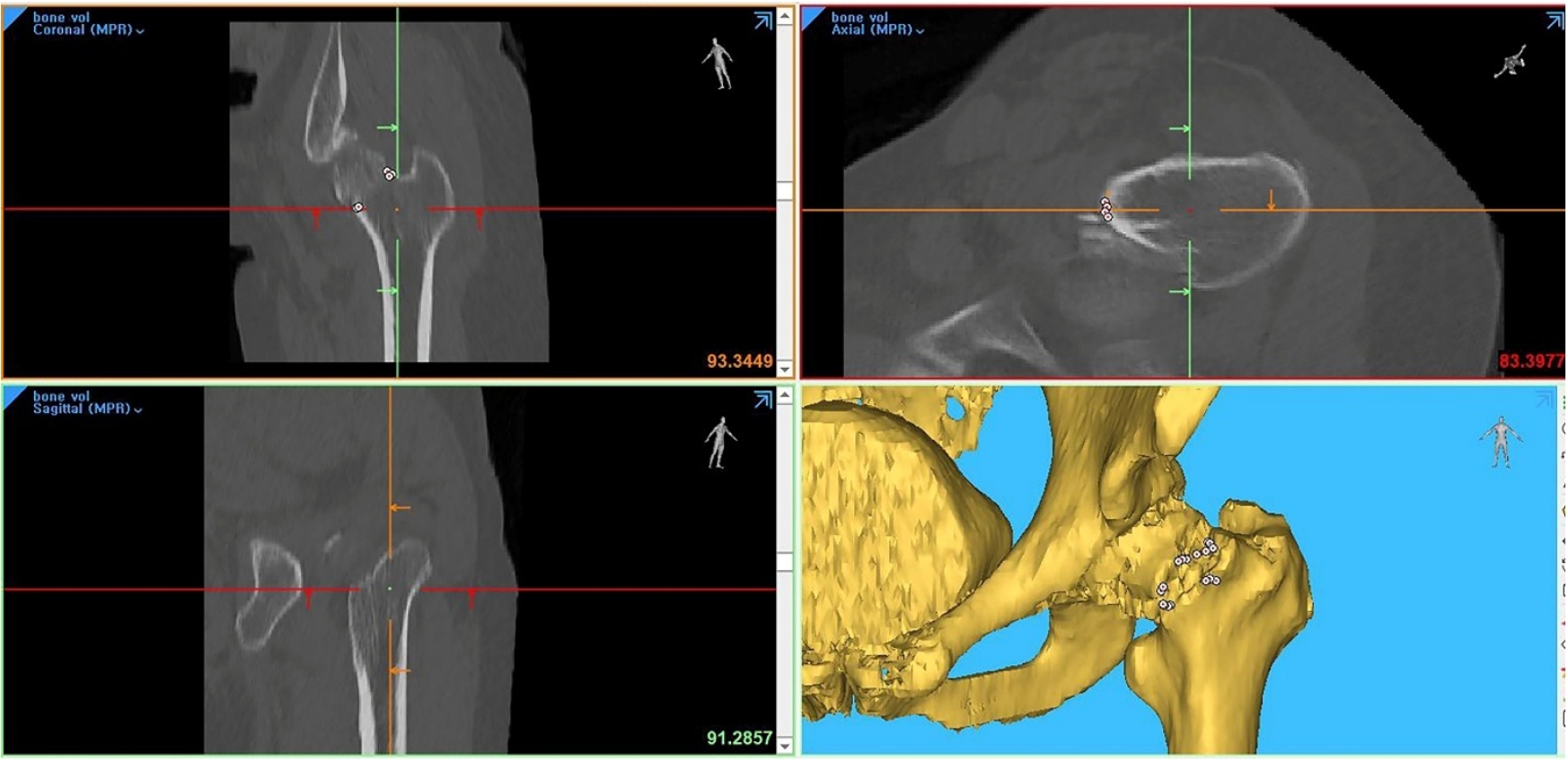
This study aimed to assess fracture verticality in both coronal and axial planes after eliminating projection error in femoral neck fractures among non-older adults, and to demonstrate its clinical utility using computed tomography (CT)-based modeling at actual size.
Methods
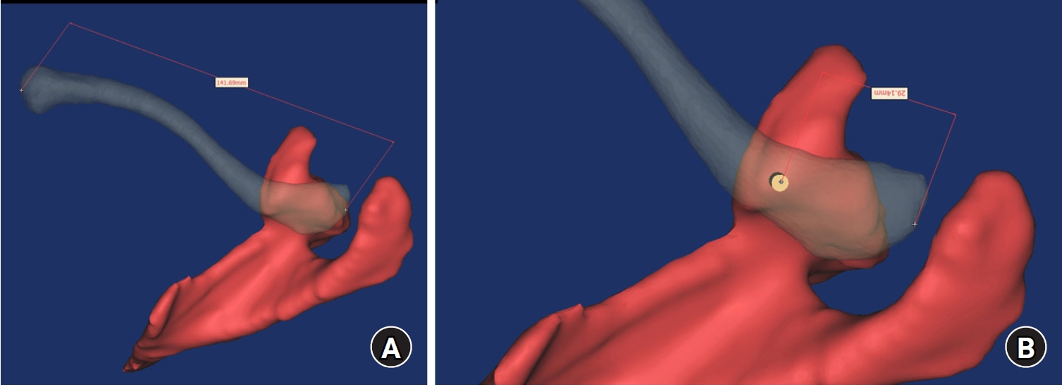
This retrospective observational study enrolled 57 patients (30 males and 27 females), aged 20–65 years, with displaced femoral neck fractures. Based on CT images, an actual-size fracture model was constructed. The CT scanning plane was reformatted with the neck-shaft fragment realigned vertically to the ground and parallel to the femoral neck axis. Three consecutive images were used to generate coronal reformats at the centerline and posterior border to measure central and posterior coronal plane verticality as Pauwels’ angle (PA). The central image of the reformatted axial plane was used to assess axial plane verticality. Differences in verticality were analyzed using analysis of variance.
Results
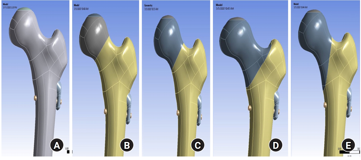
Three coronal morphology types were identified: linear (n=30), concave (n=25), and convex (n=2). Two axial morphology types were observed: cephalad (n=35) and trochanteric (n=22). The mean central PA, posterior PA, and axial verticality were 55.43°±13.79°, 51.44°±11.13°, and 85.74°±18.41°, respectively. Only the central PA showed a significant difference (P<0.001). The PA was significantly higher in the linear coronal type between images (P<0.05) and in the trochanteric axial type (P<0.05).
Conclusions
After reformatting the scanning plane, the central PA showed significant variation between images. Femoral neck fractures of the linear type in the coronal plane and the trochanteric type in the axial plane demonstrated greater verticality than other morphological types. Level of evidence:
- 516 View
- 12 Download

- Computational simulation of coracoclavicular screw insertion through the superior distal clavicular plate for clinical applications in Korean cadavers
- Hyung-Lae Cho, Ji Han Choi, Se-Lin Jeong, Gu-Hee Jung
- J Musculoskelet Trauma 2025;38(3):143-151. Published online July 22, 2025
- DOI: https://doi.org/10.12671/jmt.2025.00122
-
Abstract
PDF
- Background
The study was conducted to determine the practical area for inserting the coracoclavicular (CC) screw through the plate by analyzing three-dimensional (3D) shoulder models featuring virtually implanted, actual-size plates and screws.
Methods
Ninety cadaveric shoulders (41 males and 49 females) underwent continuous 1.0-mm slice computed tomography scans. The data were imported into image-processing software to generate a 3D shoulder model, including the scapula and clavicle. The overlapping area between the clavicle and the horizontal portion of the coracoid process (horizontal portion_CP) was analyzed in the cranial view. A curved pelvic recon plate was virtually placed on the upper surface of the distal clavicle, and an actual-size (3.5 mm) CC screw was inserted through the plate.
Results
The distal clavicle directly overlapped with the horizontal portion_CP in the vertical direction. The overlapping area was sufficient to place the 3.5 mm and 4.5 mm-sized screws. In all shoulder models, the CC screw could be inserted through the plate into the vertical direction, with an average length of 35.5 mm (range, 26.2–62.5 mm; standard deviation, 1.2 mm). In 87 models, the CC screw was inserted through the third hole from the lateral end of the plate. Two models were inserted through the second hole, and one model through the fourth hole.
Conclusions
The upper surface of the clavicle has sufficient overlapping area to place CC screws through the plate in the vertical direction in the corresponding hole. Supplemental CC screw fixation through the plate can be performed without additional or special equipment. Level of evidence: IV
- 948 View
- 23 Download
- Biomechanical finite element analysis of a femoral neck system fixation construct for femur neck fractures and clinical implications
- Hoon-Sang Sohn, Se-Lin Jeong, Gu-Hee Jung
- J Musculoskelet Trauma 2025;38(3):133-142. Published online July 22, 2025
- DOI: https://doi.org/10.12671/jmt.2025.00108
-
Abstract
PDF
- Background
This study assessed the structural/mechanical stability of fixation constructs with a femoral neck system (FNS) via finite element analysis after simulating femoral neck fractures and explored the clinical implications.
Methods
We simulated subcapital, transcervical, basicervical, and vertical fracture models using a right femur (SAWBONES) and imported the implant model of FNS to Ansys (Ansys 19.0, Ansys Inc.) to place the implant in the optimal position. The distal end of the femur model was completely fixed and was abducted 7°. The force vector was set laterally at an angle of 3° and posteriorly at an angle of 15° in the vertical ground. The analysis was conducted using Ansys software with the von Mises stress (VMS) in megapascals (MPa).
Results
The maximum VMS of the fracture site was 67.01 MPa for a subcapital, 68.56 MPa for a transcervical, 344.54 MPa for a basicervical, and 130.59 MPa for a vertical model. The maximum VMS of FNS was 840.34 MPa for a subcapital, 637.37 MPa for a transcervical, 464.07 MPa for a basicervical, and 421.01 MPa for a vertical model. The stress distribution of basicervical and vertical fractures differed significantly, and the basicervical fracture had higher VMS at the bone, implant, and fracture sites.
Conclusions
FNS fixation should be performed with consideration the osseous anchorage in the femoral head, and this technique might be appropriate for vertical fractures. Regarding the VMS at the fracture site, FNS might be applied cautiously only to basicervical fractures with anatomical reduction without a gap or comminution. Level of evidence: IV. -
Citations
Citations to this article as recorded by
- Finite element analysis of screw thread geometry and titanium plate materials in internal fixation of the human femur
Abdessamed Bachiri, Mustapha Amine Arab, Nadia Kadouri
Computer Methods in Biomechanics and Biomedical Engineering.2026; : 1. CrossRef
- Finite element analysis of screw thread geometry and titanium plate materials in internal fixation of the human femur
- 2,664 View
- 94 Download
- 1 Crossref
Review Article
- How to obtain the desired results from distal tibial nailing based on anatomy, biomechanics, and reduction techniques
- Jungtae Ahn, Se-Lin Jeong, Gu-Hee Jung
- J Musculoskelet Trauma 2025;38(2):74-85. Published online March 31, 2025
- DOI: https://doi.org/10.12671/jmt.2025.00024

-
Abstract
PDF
- Distal tibial metaphyseal fractures are commonly caused by high-energy injuries in young men and osteoporosis in older women. These fractures should be clearly distinguished from high-energy pilon fractures. Although the optimal surgical intervention methods for distal tibial metaphyseal fractures remain uncertain and challenging, surgical treatments for nonarticular distal tibia fractures can be broadly divided into two types: plate fixation and intramedullary nail (IMN) fixation. Once functional reduction is achieved using an appropriate technique, distal tibial nailing might be slightly superior to plate fixation in reducing postoperative complications. Thus, the surgical strategy should focus on functional realignment and proceed in the following sequence: (1) restoring the original tibial length, regardless of whether fibular fixation is to be done; (2) making the optimal entry point through an anteroposterior (AP) projection based on the overlapping point between the fibular tip and lateral plateau margin; (3) placing Kirschner wires (Ø2.4 mm) as blocking pins (in the AP orientation for coronal control and in the mediolateral [ML] orientation for sagittal control) as close to the upper locking hole as possible without causing further comminution on the concave aspect of the short fragment; and (4) making the the distal fixation construct with at least two ML and one AP interlocking screw or two ML interlocking screws and blocking screws. After the IMN is adequately locked, blocking pins (Ø2.4 mm) need to be replaced by a 3.5 mm screw.
-
Citations
Citations to this article as recorded by- Rigid intramedullary nailing with suprapatellar approach for tibial shaft fractures in adolescents with open physes
Jong Wha Lee, Jae Ho Cho, Tae Hun Kim, Hyung Keun Song, Won-Tae Cho, Seungyeob Sakong, Hyun Il Choi, Sumin Lim
Injury.2026; 57(4): 113130. CrossRef - Impact of Foot Width on Patient-Reported Outcomes Assessed by 3-Dimensional Foot Morphometry in Hallux Valgus
Jungtae Ahn, Dae-Cheol Nam, Gu-Hee Jung
Clinics in Orthopedic Surgery.2025; 17(6): 1062. CrossRef
- Rigid intramedullary nailing with suprapatellar approach for tibial shaft fractures in adolescents with open physes
- 4,176 View
- 94 Download
- 2 Crossref
 First
First Prev
Prev

