 E-submission
 TOTA
TOTA TOTS
TOTS
Articles
- Page Path
- HOME > J Musculoskelet Trauma > Volume 30(4); 2017 > Article
-
Original Article
- The Determination of Optimal Entry Point for Proximal Femoral Nail Antirotation-II by Fluoroscopic Simulation: A Cadaveric Study
-
Jin-Hoon Jeong, M.D.
 , Gu-Hee Jung, M.D., Ph.D.
 -
Journal of the Korean Fracture Society 2017;30(4):173-179.
DOI: https://doi.org/10.12671/jkfs.2017.30.4.173
Published online: October 25, 2017
Department of Orthopaedic Surgery, Gyeongsang National University Changwon Hospital, Gyeongsang National University College of Medicine, Changwon, Korea.
- Correspondence to: Gu-Hee Jung, M.D., Ph.D. Department of Orthopaedic Surgery, Gyeongsang National University Changwon Hospital, 11 Samjeongja-ro, Seongsan-gu, Changwon 51472, Korea. Tel: +82-55-214-3822, Fax: +82-55-214-1031, jyujin2001@hotmail.com
• Received: July 24, 2017 • Revised: August 8, 2017 • Accepted: September 27, 2017
Copyright © 2017 The Korean Fracture Society. All rights reserved.
This is an Open Access article distributed under the terms of the Creative Commons Attribution Non-Commercial License (http://creativecommons.org/licenses/by-nc/4.0) which permits unrestricted non-commercial use, distribution, and reproduction in any medium, provided the original work is properly cited.
- 3,049 Views
- 92 Download
- 2 Crossref
Abstract
-
Purpose
- This study seeks to determine the anatomically optimal entry point of proximal femoral nail antirotation-II (PFNA-II®) according to geographic features of Korean cadaveric femoral trochanters for successful reduction of osteoporotic proximal femoral fractures.
-
Materials and Methods
- Forty-three adult cadaveric femurs without previous fractures or surgeries were included. Anteroposterior (AP) and lateral images of all femurs and PFNA-II® were taken with an image intensifier. Using the image synthesis process via the image editing program (Adobe Photoshop CS6), the optimal entry point was verified and compared with the tip of the greater trochanter (GT) and the cervicotro-chanteric junction on AP images, as well as the width of the trochanter and the neck on lateral images.
-
Results
- The optimal entry point of PFNA-II® was an average distance of 9.1 mm (range, 7–15 mm) medially from the tip of GT on AP images. The center of the nail was located at an average of 30% (range, 21%–44%) area from the posterior margin of the middle neck, which is an average area of 38% (range, 26%–48%) from the posterior cortex of the trochanter on lateral images. Furthermore, the ideal entry point was at the extended line of the cervico-trochanteric junction.
-
Conclusion
- The optimal entry point, which was found to be medial to the tip of the GT and posterior to the center of the middle femoral neck and the trochanter, was at on the extended line of the cervicotrochanteric junction.
- 1. Cho HM, Lee K. Clinical and functional outcomes of treatment for type A1 intertrochanteric femoral fracture in elderly patients: comparison of dynamic hip screw and proximal femoral nail antirotation. Hip Pelvis, 2016;28:232-242.ArticlePDF
- 2. Mavrogenis AF, Panagopoulos GN, Megaloikonomos PD, et al. Complications after hip nailing for fractures. Orthopedics, 2016;39:e108-e116.Article
- 3. Aktselis I, Kokoroghiannis C, Fragkomichalos E, et al. Prospective randomised controlled trial of an intramedullary nail versus a sliding hip screw for intertrochanteric fractures of the femur. Int Orthop, 2014;38:155-161.ArticlePubMedPDF
- 4. Niu E, Yang A, Harris AH, Bishop J. Which fixation device is preferred for surgical treatment of intertrochanteric hip fractures in the United States? A survey of orthopaedic surgeons. Clin Orthop Relat Res, 2015;473:3647-3655.ArticlePubMedPMC
- 5. Tsukada S, Okumura G, Matsueda M. Postoperative stability on lateral radiographs in the surgical treatment of pertrochanteric hip fractures. Arch Orthop Trauma Surg, 2012;132:839-846.ArticlePDF
- 6. Kozono N, Ikemura S, Yamashita A, Harada T, Watanabe T, Shirasawa K. Direct reduction may need to be considered to avoid postoperative subtype P in patients with an unstable trochanteric fracture: a retrospective study using a multivariate analysis. Arch Orthop Trauma Surg, 2014;134:1649-1654.ArticlePubMedPDF
- 7. Oh JK, Hwang JH. Osteoporotic pertrochanteric fracture: IM nailing. J Korean Fract Soc, 2009;22:56-65.Article
- 8. Haidukewych GJ. Intertrochanteric fractures: ten tips to improve results. J Bone Joint Surg Am, 2009;91:712-719.
- 9. Bonnaire F, Zenker H, Lill C, Weber AT, Linke B. Treatment strategies for proximal femur fractures in osteoporotic patients. Osteoporos Int, 2005;16:Suppl 2. S93-S102.ArticlePDF
- 10. Zirngibl B, Biber R, Bail HJ. How to prevent cut-out and cutthrough in biaxial proximal femoral nails: is there anything beyond lag screw positioning and tip-apex distance? Int Orthop, 2013;37:1363-1368.ArticlePubMedPMCPDF
- 11. Miller SD, Burkart B, Damson E, Shrive N, Bray RC. The effect of the entry hole for an intramedullary nail on the strength of the proximal femur. J Bone Joint Surg Br, 1993;75:202-206.ArticlePubMedPDF
- 12. Ostrum RF, Levy MS. Penetration of the distal femoral anterior cortex during intramedullary nailing for subtrochanteric fractures: a report of three cases. J Orthop Trauma, 2005;19:656-660.ArticlePubMed
- 13. Pena OR, Gómez Gélvez A, Espinosa KA. Clinical implications of impingement of the anterior femoral cortex after cephalomedullary nailing. Injury, 2016;47:2300-2306.ArticlePubMed
- 14. Chang SM, Song DL, Ma Z, et al. Mismatch of the short straight cephalomedullary nail (PFNA-II) with the anterior bow of the femur in an Asian population. J Orthop Trauma, 2014;28:17-22.ArticlePubMed
- 15. Tao YL, Ma Z, Chang SM. Does PFNA II avoid lateral cortex impingement for unstable peritrochanteric fractures? Clin Orthop Relat Res, 2013;471:1393-1394.
- 16. Macheras GA, Koutsostathis SD, Galanakos S, Kateros K, Papadakis SA. Does PFNA II avoid lateral cortex impingement for unstable peritrochanteric fractures? Clin Orthop Relat Res, 2012;470:3067-3076.ArticlePubMedPMC
- 17. Tyagi V, Yang JH, Oh KJ. A computed tomography-based analysis of proximal femoral geometry for lateral impingement with two types of proximal femoral nail anterotation in subtrochanteric fractures. Injury, 2010;41:857-861.ArticlePubMed
- 18. Liu Y, Tao R, Liu F, et al. Mid-term outcomes after intramedullary fixation of peritrochanteric femoral fractures using the new proximal femoral nail antirotation (PFNA). Injury, 2010;41:810-817.ArticlePubMed
- 19. Socci AR, Casemyr NE, Leslie MP, Baumgaertner MR. Implant options for the treatment of intertrochanteric fractures of the hip: rationale, evidence, and recommendations. Bone Joint J, 2017;99-B:128-133.PubMed
- 20. Andruszkow H, Frink M, Fromke C, et al. Tip apex distance, hip screw placement, and neck shaft angle as potential risk factors for cut-out failure of hip screws after surgical treatment of intertrochanteric fractures. Int Orthop, 2012;36:2347-2354.ArticlePDF
- 21. Chang SM, Zhang YQ, Ma Z, Li Q, Dargel J, Eysel P. Fracture reduction with positive medial cortical support: a key element in stability reconstruction for the unstable pertrochanteric hip fractures. Arch Orthop Trauma Surg, 2015;135:811-818.ArticlePDF
- 22. Ito J, Takakubo Y, Sasaki K, Sasaki J, Owashi K, Takagi M. Prevention of excessive postoperative sliding of the short femoral nail in femoral trochanteric fractures. Arch Orthop Trauma Surg, 2015;135:651-657.ArticlePDF
- 23. Perez EA, Jahangir AA, Mashru RP, Russell TA. Is there a gluteus medius tendon injury during reaming through a modified medial trochanteric portal? A cadaver study. J Orthop Trauma, 2007;21:617-620.ArticlePubMed
- 24. Li J, Cheng L, Jing J. The Asia proximal femoral nail antirotation versus the standard proximal femoral antirotation nail for unstable intertrochanteric fractures in elderly Chinese patients. Orthop Traumatol Surg Res, 2015;101:143-146.ArticlePubMed
- 25. Sawaguchi T, Sakagoshi D, Shima Y, Ito T, Goldhahn S. Do design adaptations of a trochanteric nail make sense for Asian patients? Results of a multicenter study of the PFNA-II in Japan. Injury, 2014;45:1624-1631.ArticlePubMed
- 26. Anastopoulos G, Chissas D, Dourountakis J, et al. Computer-assisted three-dimensional correlation between the femoral neck-shaft angle and the optimal entry point for antegrade nailing. Injury, 2010;41:300-305.ArticlePubMed
- 27. Ansari Moein CM, Ten Duis HJ, Oey PL, de Kort GA, van der Meulen W, van der Werken C. Intramedullary femoral nailing through the trochanteric fossa versus greater trochanter tip: a randomized controlled study with in-depth functional outcome results. Eur J Trauma Emerg Surg, 2011;37:615-622.ArticlePDF
- 28. Ansari Moein CM, Verhofstad MH, Bleys RL, van der Werken C. Soft tissue injury related to choice of entry point in antegrade femoral nailing: piriform fossa or greater trochanter tip. Injury, 2005;36:1337-1342.ArticlePubMed
- 29. Byun YS, Jung GH. Three-dimensional correlation between trochanteric fossa and the ideal entry point for antegrade femoral nailing. Injury, 2016;47:2539-2543.ArticlePubMed
- 30. Crookshank MC, Edwards MR, Sellan M, Whyne CM, Schemitsch EH. Can fluoroscopy-based computer navigation improve entry point selection for intramedullary nailing of femur fractures? Clin Orthop Relat Res, 2014;472:2720-2727.Article
- 31. Farhang K, Desai R, Wilber JH, Cooperman DR, Liu RW. An anatomical study of the entry point in the greater trochanter for intramedullary nailing. Bone Joint J, 2014;96-B:1274-1281.ArticlePubMedPDF
- 32. Kale SP, Patil N, Pilankar S, Karkhanis AR, Bagaria V. Correct anatomical location of entry point for antegrade femoral nailing. Injury, 2006;37:990-993.ArticlePubMed
- 33. Linke B, Ansari Moein C, Bösl O, et al. Lateral insertion points in antegrade femoral nailing and their influence on femoral bone strains. J Orthop Trauma, 2008;22:716-722.ArticlePubMed
- 34. Nicolaou D, Watson JT. Nailing proximal femur fractures: how to choose starting point and proximal screw configuration. J Orthop Trauma, 2015;29:Suppl 4. S22-S27.PubMed
- 35. Ostrum RF, Marcantonio A, Marburger R. A critical analysis of the eccentric starting point for trochanteric intramedullary femoral nailing. J Orthop Trauma, 2005;19:681-686.ArticlePubMed
- 36. Chon CS, Kang B, Kim HS, Jung GH. Implications of three-dimensional modeling of the proximal femur for cephalomedullary nailing: an Asian cadaver study. Injury, 2017;[epub].Article
- 37. Lv C, Fang Y, Liu L, et al. The new proximal femoral nail antirotation-Asia: early results. Orthopedics, 2011;34:351. ArticlePubMed
- 38. Prasarn ML, Cattaneo MD, Achor T, et al. The effect of entry point on malalignment and iatrogenic fracture with the Synthes lateral entry femoral nail. J Orthop Trauma, 2010;24:224-229.ArticlePubMed
- 39. Streubel PN, Wong AH, Ricci WM, Gardner MJ. Is there a standard trochanteric entry site for nailing of subtrochanteric femur fractures? J Orthop Trauma, 2011;25:202-207.Article
- 40. Grechenig W, Pichler W, Clement H, Tesch NP, Grechenig S. Anatomy of the greater femoral trochanter: clinical importance for intramedullary femoral nailing. Anatomic study of 100 cadaver specimens. Acta Orthop, 2006;77:899-901.ArticlePubMed
REFERENCES
Fig. 1

A cadaveric adult femur that is marked with lead wires. To verify clearly through an image intensifier, the femur was marked with easily flexible lead wires on (1) the circumference of the femoral neck, (2) the cervico-trochanteric junction, and (3) the most protruded portions of anterior and posterior surfaces of the trochanter passing the tip of the greater trochanter.
Fig. 2

Image synthesis process on the anteroposterior (AP) plane with the image editing program. (A) An AP image of the femur, (B) an AP image of proximal femoral nail antirotation-II (PFNA-II®), (C) synthesized images of the femur and the cephalomedullary nail on the ideal position, (D) drew a line bisecting the proximal part of PFNA-II®, (E) checked the ideal entry point (*) of the nail on the femur, and removed the image of the nail, (F) measured the distance (d) between the ideal entry point (*) and the tip of the greater trochanter (**).
Fig. 3

Image synthesis process on the lateral plane with an image editing program. (A) A lateral image of the femur, (B) synthesized images of the femur and cephalomedullary nail on the ideal position, and drew a line bisecting the proximal part of proximal femoral nail antirotation-II (PFNA-II®), (C) measured the width of the femoral neck and the distance between a posterior cortex of the femoral neck and the center of nail, (D) measured the width of the trochanter and the distance between a posterior cortex of the trochanter and the center of nail.
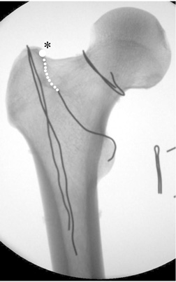
Figure & Data
REFERENCES
Citations
Citations to this article as recorded by 
- Clinical Research through Computational Anatomy and Virtual Fixation
Ju Yeong Kim, Dong-Geun Kang, Gu-Hee Jung
Journal of the Korean Orthopaedic Association.2023; 58(4): 299. CrossRef - Does the Entry Point of Proximal Femoral Nail Antirotation Affect the Malalignment of Intertrochanteric Fracture? A Cadaveric Study
Chittawee Jiamton, Nonpawit Nimmankiatkul, Pongsakorn Rungchamrassopa, Wichan Kanchanatawan, Pariyut Chiarapatanakom, Wirat Kongcharoensombat
Journal of Southeast Asian Orthopaedics.2022;[Epub] CrossRef
 Cite
CiteThe Determination of Optimal Entry Point for Proximal Femoral Nail Antirotation-II by Fluoroscopic Simulation: A Cadaveric Study
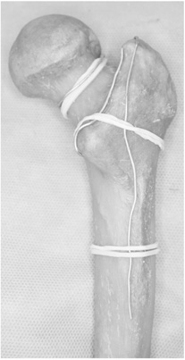
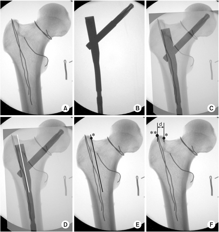
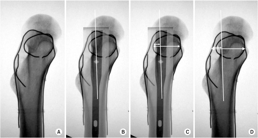

Fig. 1
A cadaveric adult femur that is marked with lead wires. To verify clearly through an image intensifier, the femur was marked with easily flexible lead wires on (1) the circumference of the femoral neck, (2) the cervico-trochanteric junction, and (3) the most protruded portions of anterior and posterior surfaces of the trochanter passing the tip of the greater trochanter.
Fig. 2
Image synthesis process on the anteroposterior (AP) plane with the image editing program. (A) An AP image of the femur, (B) an AP image of proximal femoral nail antirotation-II (PFNA-II®), (C) synthesized images of the femur and the cephalomedullary nail on the ideal position, (D) drew a line bisecting the proximal part of PFNA-II®, (E) checked the ideal entry point (*) of the nail on the femur, and removed the image of the nail, (F) measured the distance (d) between the ideal entry point (*) and the tip of the greater trochanter (**).
Fig. 3
Image synthesis process on the lateral plane with an image editing program. (A) A lateral image of the femur, (B) synthesized images of the femur and cephalomedullary nail on the ideal position, and drew a line bisecting the proximal part of proximal femoral nail antirotation-II (PFNA-II®), (C) measured the width of the femoral neck and the distance between a posterior cortex of the femoral neck and the center of nail, (D) measured the width of the trochanter and the distance between a posterior cortex of the trochanter and the center of nail.
Fig. 4
Ideal entry point (*) was at the extended line of the cervicotrochanteric junction.
Fig. 1
Fig. 2
Fig. 3
Fig. 4
The Determination of Optimal Entry Point for Proximal Femoral Nail Antirotation-II by Fluoroscopic Simulation: A Cadaveric Study

